Instructions for Connecting Telephone Sockets
Preparation:
Gather the necessary tools, including a screwdriver (a Phillips screwdriver is ideal), cable cutters, and wire strippers.
Preparation of the Telephone Line:
Locate the end of the telephone line that will be connected to the telephone socket. Typically, there is a small plastic cover at the end of the line.
Carefully remove the plastic cover to expose the wires. Usually, you will find four wires: red, green, yellow, and black.
Connecting the Telephone Line:
Take the TAE telephone socket and open it by loosening the screws at the top and bottom of the cover.
Inside the telephone socket, you will find four terminal blocks or screw terminals labeled as: a, b, c, and d.
Take the red wire and connect it to terminal a. Loosen the screw terminal, insert the wire, and tighten the screw to establish a secure connection. Repeat this process for the other three wires: green to terminal b, yellow to terminal c, and black to terminal d.
Ensure that the wires are securely attached to the terminals and no wire is protruding.
Finishing:
Close the telephone socket by replacing the cover and tightening the screws at the top and bottom.
Double-check that all wires are properly attached to the terminals.
Test the telephone socket by connecting a telephone and verifying if you can establish a connection.
Overview of Telephone Sockets:
For a conventional telephone connection using a TAE socket, the incoming line is connected to terminals 1 and 2.
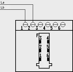
TAE Circuit Diagram
Double Connections:
For a double connection with TAE NFF, the first line is connected to the upper terminal block, and the second line is connected to the lower terminal block.
When devices are connected to an NFN socket, only one of them can be used at a time. When a device is plugged into an N socket and activated, the devices connected behind it are disconnected from the line. For example, if a conventional modem is active in the left N socket, the right N socket and the F socket are disabled.
The same applies to the left and middle sockets of an NFF socket. A modem in the N socket can disable the telephone in the middle socket but not the one in the right socket, as it is electrically independent of the other two sockets.
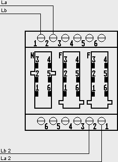
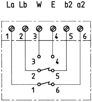
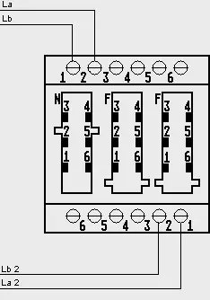
TAE NFF Circuit Diagram TAE-F Circuit Diagram TAE-NFF Circuit Diagram
TAE Socket System
In a TAE socket system, the incoming line is connected to terminals 1 and 2.
The additional pair of wires is connected from 6 to 1 and from 5 to 2.
It should be noted that when using an F-coded device, the rest of the socket system will be deactivated. If the system is intended to operate multiple N-coded devices as well as an F-coded device, the TAE-F socket must be connected at the end of the system.
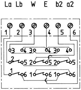
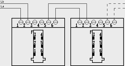
TAE-NFN Circuit Diagram Circuit