Dahlander circuit: two speed steps

A Dahlander contactor circuit selects two speed levels on a purpose-built three-phase induction motor. It reconnects a special stator winding to change the effective pole count. It does not provide continuously variable speed or turn an arbitrary motor into a two-speed machine.
This page explains pole changing, the existing functional illustration and the requirements for contactors, transitions and checks. Actual connections always depend on the particular Dahlander motor.
Circuit diagrams and explanations
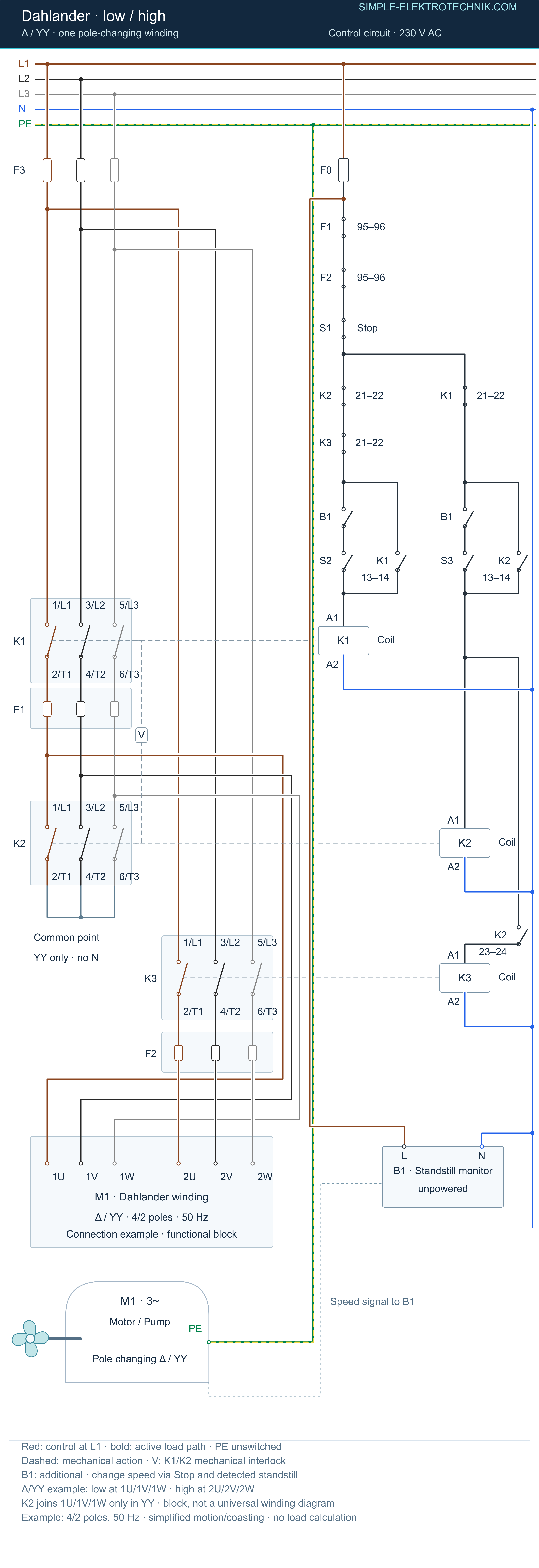
At low speed, K1 holds through its auxiliary NO contact. At high speed, K2 holds through 13–14 and enables K3 through its additional NO contact 23–24. These assignments apply to the illustrated example. F1 and F2 monitor the different supply paths; their shutdown contacts precede the start/holding branches. K1 is electrically and mechanically interlocked against the high-speed combination.
Construction and operation

One reconnectable winding, two pole counts
A Dahlander motor uses one interconnected, reconnectable winding system. Changing the relationship between its sections changes pole count in a 2:1 ratio. At a fixed supply frequency, the corresponding synchronous speeds have a 1:2 ratio.
Synchronous speed is the speed of the rotating magnetic field. In motoring operation, an induction motor runs slightly slower because of slip. Its two actual nameplate speeds therefore need not have an exact 1:2 ratio.
For example, at 50 Hz a four-pole field has a synchronous speed of 1500 rpm, while a two-pole field has 3000 rpm. These are not universal operating speeds for every Dahlander motor. Here pole count means the total number of poles, not the number of pole pairs.
Different winding versions exist
A common arrangement is Δ/YY: delta at low speed and double star at high speed. Other winding designs include Y/YY for particular load characteristics. Power and torque characteristics follow the motor design; the name Dahlander alone does not determine them.
A motor with two electrically separate windings is a different construction. Six terminals or a star symbol do not by themselves identify a Dahlander winding.
The contactors establish the required winding connections. Power contacts switch motor current; auxiliary contacts provide functions such as holding, indication and interlocking. An additional control relay is needed only if the actual control design requires it.
Functional illustration and explanation
The existing image is deliberately a functional overview of a Δ/YY example. K1 represents low-speed delta operation on the left. K2 and K3 together represent high-speed double-star operation on the right. These references explain the example, not a universal manufacturer assignment.
The internal winding is deliberately represented as a functional block. The model does not identify an unknown existing motor. Verify its actual winding and terminal markings against the applicable manufacturer diagram.
Basic states of the illustrated example
| State | K1 low-speed group | K2 and K3 high-speed group | Meaning |
|---|---|---|---|
| Off | Off | Both off | No operating speed selected |
| Low speed | On | Both off | Intended delta stage |
| High speed | Off | Both on | Intended double-star stage |
| Incompatible combination | On | High-speed group also active | Prohibited; prevent through the control design |
This is a functional overview, not a switching instruction. Transitions and any intermediate states require the matching verified drawing. Showing both speeds side by side does not permit simultaneous operation.
Additional delta/double-star examples
The new connection overview defines a suitable delta/double-star example: K1 supplies 1U/1V/1W for low speed. At high speed K2 joins those points and K3 supplies the intended 2U/2V/2W terminals. The actual winding must match that documented allocation. No invented internal winding drawing is added.
At low speed, K1 holds through its auxiliary NO contact. At high speed, K2 holds through 13–14 and enables K3 through its additional NO contact 23–24. These assignments apply to the illustrated example. F1 and F2 monitor the different supply paths; their shutdown contacts precede the start/holding branches. K1 is electrically and mechanically interlocked against the high-speed combination.
Additional B1 enables starts only after detected standstill here. Speed changes are via Stop; the opposite command alone does not end the active speed. This deliberately chosen variant is not inherent in every Dahlander control. The motor’s terminal diagram remains decisive; six visible terminals alone do not establish its type.
The state illustration shows Off, Low and High. Change only through the intended stop sequence and required machine conditions. Pauses, protection, settings and mechanical interlocks depend on the motor and application. The new example defines its own allocation without claiming to identify an unknown real motor from a photograph.
This model uses a documented Δ/YY example with 1U/1V/1W and 2U/2V/2W. K1 supplies the first group for low speed. At high speed, K2 joins that group into a common point while K3 supplies the second group. The internal winding remains a functional block.
Wiring principles and selection
Wiring and transition conditions
Identify the motor type, winding arrangement and permitted operating modes first. Then assign contactor functions, motor conductors, control circuits and protection. The normal three-phase winding does not require neutral simply because N appears among the available conductors. Assess the control supply separately. Its place among different motor-control tasks is discussed in the contactor circuit comparison.
Interlocking prevents incompatible low- and high-speed combinations. The actual circuit determines which contactors must operate together and which must exclude one another. Indiscriminately interlocking all three against each other would be wrong when two are required together for one speed.
The motor and driven machine determine whether changing speed while running is allowed, the required sequence and any delay. Changing from high to low speed can impose substantial current and torque demands. Direct changeover is not an automatic capability of every Dahlander arrangement.
Protection must cover both speed levels. Rated currents may differ; one unchecked setting based on the higher-speed rating does not automatically protect the lower-speed condition correctly. Suitable solutions may use purpose-designed protective equipment or separate current sensing. Follow the manufacturer documentation and complete circuit.
Before access, account for every supply and possible machine movement. The five safety rules and appropriate competence apply to two-speed drives as well.
Additional B1 enables starts only after detected standstill here. Speed changes are via Stop; the opposite command alone does not end the active speed. This deliberately chosen variant is not inherent in every Dahlander control. The motor’s terminal diagram remains decisive; six visible terminals alone do not establish its type.
Functional checks and verification

Begin with motor and component data, inspection and the required electrical verification. Then check the permitted operating modes with machine hazards controlled.
- Each speed must establish and release its intended contactor combination.
- Compare direction and actual speed with the machine requirements and motor data. A higher current alone does not identify a correct speed stage.
- Test only permitted transitions, using the designed sequence. Do not bypass interlocks.
- Operating currents, protective settings, stopping and restart behaviour must cover both speeds.
- Investigate abnormal noise, severe transition shock or unacceptable heating. Isolate and secure the equipment before correcting connections.
A functional test establishes only the functions actually tested. It does not replace electrical safety verification or assessment of machinery movement hazards.
Try the interactive model
- Start and latch low speed; try the opposite command.
- Stop, follow coasting and B1, then start high speed.
- Observe K2/K3 as the high-speed pair and the separate protection paths.
- Trip F1 and F2 individually; distinguish reset with Start free from starting again.
Advantages and limitations

Benefits depend on suitable design. Contact duty, protection and behaviour after interruption must match the application.
Advantages
- A suitable winding and switching assembly provide two defined operating points.
- An electromechanical arrangement can be appropriate where exactly two speeds are sufficient.
- A documented contactor circuit makes operating states and interlocks understandable.
Limitations
- Only the designed speed steps are available.
- The motor must be built for the required pole-changing arrangement.
- Changes of speed impose electrical and mechanical stress; transition conditions and switching frequency are limited.
- Contacts wear. Cost, efficiency and reliability depend on the application and are not automatically superior to every variable-frequency drive.
Limits of this learning model
At a fixed frequency, the 4/2-pole example halves pole count and doubles synchronous speed. At 50 Hz, four and two poles correspond to 1500 and 3000 min⁻¹ synchronously. Nameplate running speeds differ because of slip. Only the intended steps are available; switching stress and protection must cover both.
The model explains a functional example. Real installation work requires appropriate competence, authorisation and safe working procedures; normal Stop is not safe isolation. Functional testing and electrical safety verification remain separate.
Questions and related guides
Is Dahlander operation the same as star–delta starting?
No. Star–delta starting keeps the same pole count and changes winding voltage during starting. Dahlander operation changes effective pole count to provide two speeds.
Can extra contactors convert an ordinary motor?
Not merely by changing external connections. The required winding must already be part of the motor design. Any permissible modification needs reliable motor information.
Can the motor direction also be reversed?
Pole changing and direction selection are separate functions. They can be combined in a specifically designed complete circuit. The reversing contactor circuit explains the direction-control principle.
Related guides
Direct-on-line starting of a three-phase motor · Reversing contactor circuits
Further related explanations
- Difference from star-delta
- Direction selection
- Compare contactor circuits
- Contactor circuits overview
- Schneider Electric: Zwei-/Dreileitersteuerung / Two- and three-wire control
- VEM: Klemmenplan / Terminal diagram KP 0003 Δ/YY
Further context: Relays and contactors · Functional testing
Sources and documentation
Electrical safety: scope, competence and precautions
Put electrical safety first.
- These explanations and simplified diagrams support learning. They are not complete installation designs, site-specific risk assessments or a substitute for competent professional assessment.
- Electrical work can be life-threatening. It requires the competence and authorisation appropriate to the actual task, installation and jurisdiction.
- Errors and omissions can occur. Check the actual equipment documentation, applicable requirements and the complete installation before relying on an example; a working device is not proof of electrical safety.
- Personal protective equipment must suit the assessed hazards and task. It does not replace isolation, appropriate tools, competence or a safe system of work.
- Do not work on exposed live parts on the basis of these guides. Identify every relevant source, isolate it, secure against reconnection and prove dead using suitable equipment and procedures before access.
- Responsibilities for design, installation and verification must be established for the actual work. A website statement does not determine liability or remove duties under applicable law.
- This summary is not exhaustive. Where the circuit, condition or protective arrangement is uncertain, obtain suitable professional assistance before work proceeds.
- Complete the required inspection, testing and documentation before use, and maintain the installation and equipment appropriately.
Electrical terms explained
Electric current
The rate of flow of electric charge, measured in amperes (A). Conventional current direction follows positive charge flow, which is opposite to electron drift in a metallic conductor.
Voltage
The electric potential difference between two points, measured in volts (V). Always identify the reference points, such as line-to-neutral or line-to-earth; a voltage is not a property of one isolated terminal alone.
Resistance
The opposition associated with resistive current flow, measured in ohms (Ω). For a component behaving as an ohmic resistance under the stated conditions, U = IR.
Electrical power
The rate of electrical energy transfer, measured in watts (W). P = UI applies to steady DC; in a sinusoidal single-phase AC circuit, active power is UI cos φ using RMS values. The general average depends on voltage and current waveforms.
Ohm's law
For an ohmic resistance, current is proportional to the applied voltage: I = U/R. Resistance can vary with temperature, and non-linear devices do not necessarily obey one constant-resistance relationship.
Kirchhoff's laws
The current law expresses charge conservation at a circuit node. The voltage law states that the algebraic sum of voltages around a closed loop is zero within the applicable circuit model; induced effects must be represented appropriately.
Direct current (DC)
Current that maintains one direction. Its magnitude may be constant or vary; pulsating DC is still distinguished from current that reverses direction.
Alternating current (AC)
Current whose direction reverses with time, commonly periodically. Public supplies normally use approximately sinusoidal AC, while electronic equipment can produce other waveforms.
Frequency
The number of cycles per second of a periodic quantity, measured in hertz (Hz). Many European public supplies operate at a nominal 50 Hz.
Phase difference
The relative position of periodic quantities of the same frequency, often expressed in degrees or radians. For sinusoidal quantities, a time displacement can be related to that phase angle.
Circuit diagram
A drawing representing circuit components and their electrical connections using symbols. It is distinct from a physical layout or a complete installation design.
Capacitor
A component that stores energy in an electric field. Its capacitance relates stored charge to voltage under the stated conditions; a practical capacitor also has voltage, current and other operating limits.
Strappers in lighting circuits
The pair of conductors linking the changeover contacts in conventional two-way lighting switching, including intermediate switching where used. They carry the alternative switching paths and are not transformer windings; identify their actual functions from the circuit.
Coil or winding
A conductor arranged in turns, commonly to produce magnetic effects. Its behaviour includes inductance as well as the resistance and other properties of the actual winding.
Inductance
The relationship between flux linkage and current in the applicable model, measured in henries (H). Changing current produces an induced voltage; for a constant inductance its magnitude relates to L di/dt with the appropriate sign convention.
Capacitance
The relationship between stored charge and voltage, measured in farads (F). For a constant capacitance, changing voltage produces current according to i = C dv/dt.
Transistor
A semiconductor device used for switching, amplification or other control functions. Its operating principle and control quantities depend on whether it is, for example, a bipolar transistor or a field-effect device.
Semiconductor
A material whose electrical behaviour can be controlled through composition, electric fields, light or other conditions. Semiconductor devices use this behaviour for functions such as rectification, switching and amplification.
Diode
A device with a strongly directional current-voltage characteristic. Real diodes have forward losses, reverse leakage and limits; they do not act as perfect one-way valves at every voltage.
Relay
A device that changes an output in response to a control input. An electromechanical relay uses a coil and contacts, while a solid-state relay uses electronic switching elements.
Switch
A device that makes, breaks or changes electrical connections. Its rating, contact arrangement and permitted duty determine the applications for which it is suitable.
Electrical network
An interconnection of electrical components and branches. Series, parallel and more complex arrangements can be analysed with an appropriate circuit model.
Transformer
A device transferring energy between magnetically coupled windings through changing flux. Turns ratio influences voltage and current relationships; losses, limits and any conductive connection depend on its construction.
Electromagnet
A magnetic arrangement energised by electric current, commonly using a coil and magnetic core. Contactors, relays and actuators use electromagnetic force for mechanical operation.
Impedance
The relationship between voltage and current phasors in a sinusoidal steady-state model, measured in ohms. It combines resistance and reactance and can vary with frequency.
Short circuit
An unintended low-impedance connection between points at different potentials. Current is limited by the complete source and fault-path impedance, not literally unrestricted.
Electric circuit
An arrangement of sources, conductors and components. Current flows where a complete conductive path exists, although a circuit can also be described in an open or disconnected state.
Series connection
Components in one unbranched path carry the same current. Their voltages add algebraically; the individual voltage shares depend on their electrical behaviour.
Parallel connection
Branches connected between the same two nodes share the same voltage. The branch currents depend on their loads and add algebraically at the connection points.
Fuse
An overcurrent protective device with an element designed to melt and interrupt the circuit under specified conditions. Its rating, characteristic and breaking capacity must suit the application.
Overcurrent protection
Protection against overload and short-circuit effects, commonly using fuses or circuit-breakers. A sensing relay may require a separate interrupting device; an ordinary RCCB does not provide this protection by itself.
Earthing
A deliberate connection of a system point or conductive part to earth. Protective earthing forms part of an electric-shock protection arrangement; it must not be confused with neutral, functional earth or a guarantee of zero touch voltage.
Frequency converter or variable-speed drive
Electronic equipment that produces a controlled output frequency, commonly with controlled voltage, to operate a suitable motor. Its pulsed output, protection and compatibility requirements differ from a direct mains supply.
Electromagnetic compatibility (EMC)
The ability of equipment to operate satisfactorily in its electromagnetic environment without causing unacceptable disturbance to other equipment. Both emissions and immunity matter.
Power loss
Energy dissipated per unit time, commonly as heat in conductors, cores, insulation or semiconductor devices. Ideal inductors and capacitors exchange stored energy without average loss; practical components have additional loss mechanisms.
Short-circuit current
The current resulting from a short circuit. Prospective fault current is assessed to select protective devices with adequate interrupting capability and to check thermal and mechanical effects.
Power factor
The ratio of active power to apparent power. For sinusoidal voltage and current it equals cos φ; with distortion it also reflects waveform effects. It is not the same as energy-conversion efficiency.
Insulation resistance
Resistance measured between specified conductive parts separated by insulation under stated test conditions. The test voltage, connected equipment and interpretation must suit the circuit; it is not a complete assessment of insulation performance on its own.