Instructions for installing and connecting a control changeover switch:
A control changeover switch is a variation of the conventional changeover switch that features a pilot lamp to visually indicate the switching state.
This is particularly useful for determining whether an electrical load, such as a lamp, is turned on or off. Here are instructions on how to install and connect a control changeover switch.
Structure and operation of a control changeover switch:
A control changeover switch has the same basic structure as a conventional changeover switch, but it includes an additional pilot lamp to indicate the switching state visually. The operation of the control changeover switch is identical to that of the conventional changeover switch.

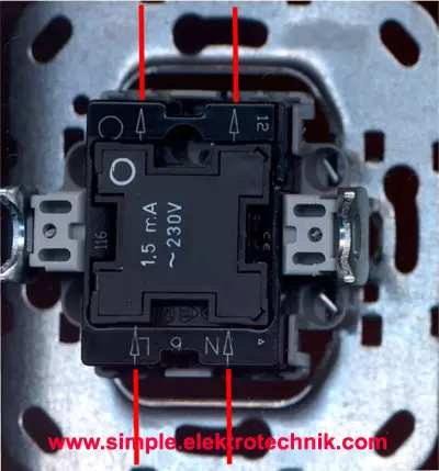
The control changeover switch consists of four terminals:
- The input terminal (L)
The input terminal is connected to the line conductor (phase) of the circuit. - The input terminal (N)
The input terminal (N) is connected to the neutral conductor of the circuit. - Two output terminals
The output terminals are usually labeled as "↓" and "↓".
In one position of the switch, the input terminal is connected to output terminal 1, while output terminal 2 is disconnected. This turns on the electrical load, such as a lamp.
When the switch is switched to the other position, the connection is reversed. Now the input terminal is connected to output terminal 2, while output terminal 1 is disconnected. This turns off the electrical load.
The control changeover switch has a pilot lamp connected in parallel with the electrical load. When the load is turned on, the pilot lamp illuminates, indicating the on state. When the load is turned off, the pilot lamp goes out.
The pilot lamp can be integrated directly into the control changeover switch or connected as a separate component. It serves as a visual indicator to monitor the switching state of the load and, for example, check whether a lamp is turned on or off.
It is important to connect the control changeover switch according to the manufacturer's instructions and ensure that all electrical connections are properly made. If you are unsure or unclear, always consult a qualified electrician to ensure safe and correct installation.
Proper wiring of a control changeover switch:
Properly wiring a control changeover switch requires special attention to ensure that both the switch state and the pilot lamp function correctly. Here is a straightforward guide for the proper wiring of a control changeover switch:

- Remove the cover of the switch box. Carefully remove the cover of the switch box where the control changeover switch will be installed. Make sure the power supply remains switched off.
- Note the terminals of the control changeover switch. Check the terminals on the control changeover switch. Typically, there are three terminals: the input terminal (L), output terminal 1 (↓), and output terminal 2 (↓). Ensure that you can correctly identify the terminals.
- Connect the input terminal. Connect the line conductor (phase) of the circuit to the input terminal (L) of the control changeover switch.
- Connect the input terminal (N). Connect the neutral conductor of the circuit to the input terminal (N) of the control changeover switch.
- Connect output terminal 1: Connect output terminal 1 (↓) of the control changeover switch to the load or lamp to be controlled.
- Output terminal 2. Output terminal 2 (↓) of the control changeover switch is only necessary if you have a second switch location. In that case, both outputs of the first control changeover switch must be connected to the corresponding wires of the second control changeover switch.
- Check the connections. Carefully check that all connections are secure and tight. Ensure that no wires are exposed and that all terminals are properly covered to avoid potential hazards.
- Turn the power supply back on. Once all connections have been checked, turn on the power supply for the area. Test the control changeover switch to ensure that both the switch state and the pilot lamp function correctly.
Note: Electrical work should always be carried out by a qualified electrician. If you feel unsure about the installation, seek professional assistance to avoid accidents or damages.
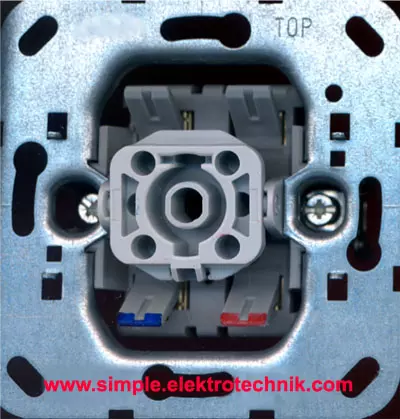
Backside of the control changeover switch
Output 1 Output 2

Terminal for the line conductor Neutral conductor
Frontside of the control changeover switch

Instructions for installing and connecting a control changeover switch:
A control changeover switch is a variation of a changeover switch that includes a pilot lamp to control the switching state. Here are instructions on how to correctly install and connect a control changeover switch:

- Make sure the power supply for the circuit where the control changeover switch will be installed is switched off. Turn off the corresponding circuit breaker or remove the fuse.
- Take the control changeover switch out of the packaging and check that it is complete and undamaged.
- Remove the cover of the switch box to access the wiring.
- Identify the terminals on the control changeover switch. Typically, there are four terminals: the input terminal (L), output terminal 1 (↓), output terminal 2 (↓), and the neutral conductor terminal (N).
- Check the manufacturer's schematic diagram to identify the correct terminals. The input terminal is usually labeled as "L," while the output terminals may be labeled as "↓" and "↓".
- Connect the input terminal of the control changeover switch to the line conductor (phase) of the circuit. Ensure the connection is secure and tight.
- Connect the neutral conductor terminal of the control changeover switch to the neutral conductor of the circuit. Ensure the connection is secure and tight.
- Connect output terminal 1 of the control changeover switch to the phase of the load to be controlled, such as a lamp.
- Connect the pilot lamp in parallel with the load. Check the manufacturer's schematic diagram to identify the exact connection for the pilot lamp. Note that some control changeover switches already have the pilot lamp integrated internally.
- Output terminal 2 of the control changeover switch is not currently used. This terminal comes into play when using two control changeover switches in different locations. In that case, both output terminals of the first control changeover switch must be connected to the corresponding terminals of the second control changeover switch. These connections are referred to as "corresponding wires".
- Carefully check that all connections are secure and tight. Use appropriate connectors or screw connections.
- Reattach the cover of the switch box.
- Turn the power supply back on by switching on the circuit breaker or inserting the fuse.
- Test the control changeover switch to ensure it functions properly. Turn the load on and off by operating the control changeover switch. The pilot lamp should indicate the switching state.
If you are unsure or have no experience with electrical installations, seek the assistance of a qualified electrician to perform the installation correctly and safely. Safety always comes first.
A control changeover switch enhances the functionality of a conventional changeover switch

By incorporating a pilot lamp to control the switching state. Here is a list of applications where a control changeover switch is particularly useful:
- Lighting control. A control changeover switch is ideal for controlling lighting circuits. It allows for easy switching on and off of lights from different positions and provides visual feedback on the switching state.
- Staircase lighting. In staircases, it is important to control the lights from different floors or sections. A control changeover switch offers the convenience of operating the lighting and visually verifying the switching state.
- Corridor circuits. Long hallways or corridors can be effectively illuminated using a control changeover switch. The switches can be placed at different positions to control the lights, and the pilot lamp enables easy monitoring of the switching state.
- Multiple switch circuits. In rooms with multiple entrances or large areas, control changeover switches are ideal for controlling the lights from different switch positions. This allows the lighting to be turned on and off at different locations, while the pilot lamp indicates the switching state.
- Outdoor lighting. Control changeover switches are also suitable for controlling outdoor lighting, such as patio or garden areas. They provide a convenient way to turn on the lights and monitor the switching state.
Thanks to the pilot lamp, control changeover switches offer enhanced control and monitoring of the switching state, making them highly useful in various applications.
Elektrosicherheit: Richtlinien und Vorsichtsmaßnahmen für einfache elektrotechnische Arbeiten
Die Sicherheit hat oberste Priorität.

- Alle hier bereitgestellten Anleitungen und Informationen dienen rein informativen Zwecken und sollen ausschließlich zur Informationsbeschaffung und Weiterbildung verwendet werden. Sie sollten nicht als Ersatz für professionelle Beratung angesehen werden. Bei Zweifeln empfiehlt es sich, einen qualifizierten Elektriker hinzuzuziehen, um fachkundige Unterstützung zu erhalten.
- Es ist wichtig, die örtlichen Vorschriften und Bestimmungen bei elektrischen Arbeiten zu beachten. Arbeiten mit Strom sollten nur von qualifizierten Fachleuten durchgeführt werden, da sie lebensgefährlich sein können.
- Fehler in Anleitungen und Schaltbildern sind möglich. Der Anbieter übernimmt keine Gewähr oder Haftung für Schäden oder Verletzungen, die aus der Umsetzung der bereitgestellten Informationen resultieren könnten. Es liegt in Ihrer Verantwortung, die Richtigkeit der Informationen zu überprüfen und die erforderlichen Sicherheitsvorkehrungen zu treffen.
- Die Verwendung geeigneter persönlicher Schutzausrüstung (PSA) ist entscheidend, um die Sicherheit bei elektrotechnischen Arbeiten zu gewährleisten. PSA schützt vor Stromschlägen, Augenverletzungen, thermischen und mechanischen Gefahren. Es ist jedoch wichtig zu beachten, dass PSA allein nicht ausreicht und durch Fachwissen, Fähigkeiten und die Einhaltung von Sicherheitsvorschriften ergänzt werden muss.
- Arbeiten an Teilen, die unter Spannung stehen, sind strengstens untersagt. Vor Beginn der Arbeiten müssen geeignete Sicherheitsvorkehrungen getroffen werden, einschließlich des Freischaltens der Anlage.
- Bei Schäden durch mangelhafte Elektroinstallation haftet der Errichter der Anlage gemäß den geltenden gesetzlichen Bestimmungen.
- Diese Zusammenfassung von Richtlinien und Vorsichtsmaßnahmen ist nicht umfassend. Bei Unsicherheiten ist es ratsam, einen qualifizierten Elektriker zu konsultieren oder sich an örtliche Vorschriften und Bestimmungen zu halten, um maximale Sicherheit zu gewährleisten.
- Die ordnungsgemäße Installation und Wartung von elektrischen Anlagen und Geräten ist von großer Bedeutung, um mögliche Gefahren zu minimieren und ein sicheres Umfeld zu schaffen.