Polarity in Sockets and Connectors: Understanding and Applying Correctly
Polarity (Direction of Rotation), An Important Electrical Property
The Schuko plug in electrical engineering is a well-known type of plug, but it is not polarity-safe. This means that by simply rotating the plug by 180°, the live conductor (phase) and neutral conductor can be interchanged.
During the introduction of the Schuko system, the polarity of the live conductors did not play a significant role, as the use of a delta voltage of 220 V was common at that time. In this system, both the live conductor and the neutral conductor had the same voltage with respect to the earth, so it was not necessary to distinguish between the two conductors.
In modern TN systems, which are widely used today and utilize a star voltage of 230 V, the live conductor carries the full voltage with respect to the earth. However, the neutral conductor is grounded through the equipotential bonding bar of the house installation. As the neutral conductor carries current, it has a higher voltage compared to the protective earth (ground) conductor.
Unlike the Schuko plug, all newer plug standards, such as the IEC 60906-1 system proposed in 1986 as a worldwide standardized solution, are designed to be polarity-safe. These modern systems offer the advantage that a single-pole circuit breaker can disconnect all live conductors that carry voltage with respect to the earth.
This ensures that the voltage is always present at the contact of a light bulb's base and not at the easily touchable thread, and that there is no voltage present at the socket when it is switched off. With the Schuko system, this depends on the direction in which the plug is inserted into the socket.
There is no regulation specifying which side of a Schuko socket the live conductor must be connected to. However, it is recommended to follow a consistent approach within an installation and always connect the live conductor to the same side. This uniform approach increases safety and avoids potential confusion.
Polarity / Direction of Rotation of CEE Power Sockets and Plugs
To enlarge the images, simply click on the images
Polarity / Direction of Rotation of Schuko Plugs, Sockets, and Connectors
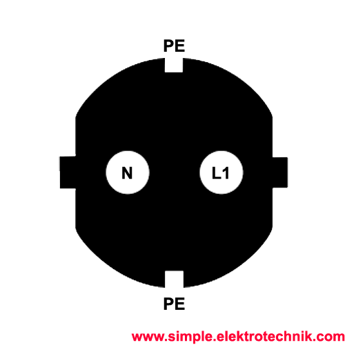
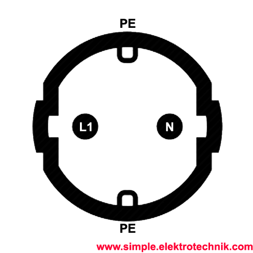
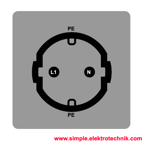
In Schuko plugs, sockets, or connectors, there is no fixed polarity. The plugs and sockets are symmetrical in design, meaning there is no specific direction in which the plug must be inserted. You can rotate the Schuko plug by 180 degrees and insert it into the socket without any difference in functionality or safety.
The reason for this lack of polarity is the way Schuko plugs and sockets are designed. They have two round pins (live conductor and neutral conductor) and one oblique grounding contact. The round pins are arranged in a way that it doesn't matter in which direction they are inserted, as the electric current can flow in both directions.
This symmetrical design ensures high user-friendliness and flexibility since devices and electrical connections do not need to be inserted in a specific orientation. It also simplifies the installation and operation of devices as there is no need to consider which side of the plug or socket functions as the live conductor or neutral conductor.
To enlarge the images, simply click on the images
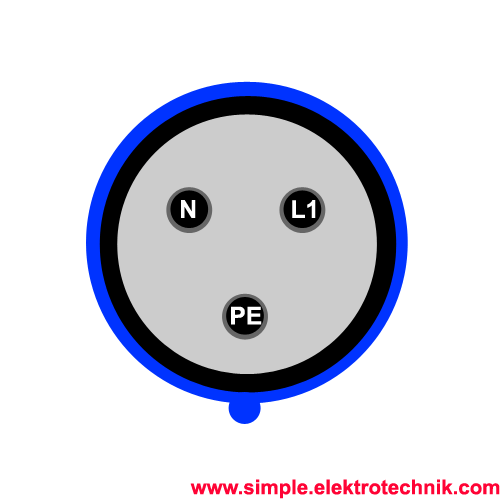
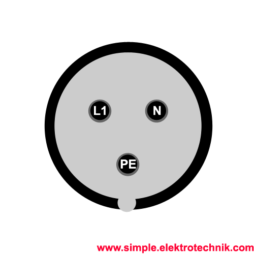
Polarity / Rotation Direction of Type 13 / Type 23 Plugs, Sockets, and Connectors
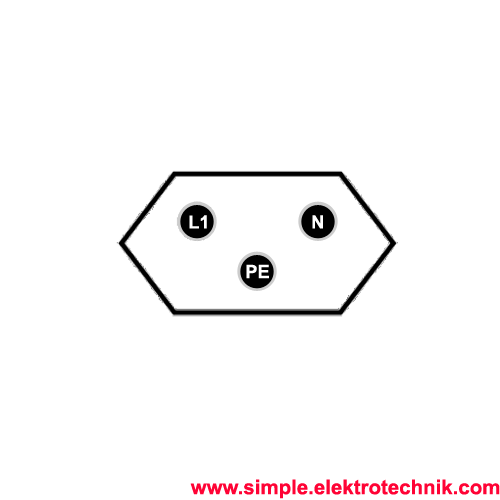
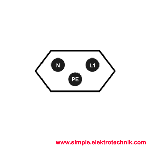
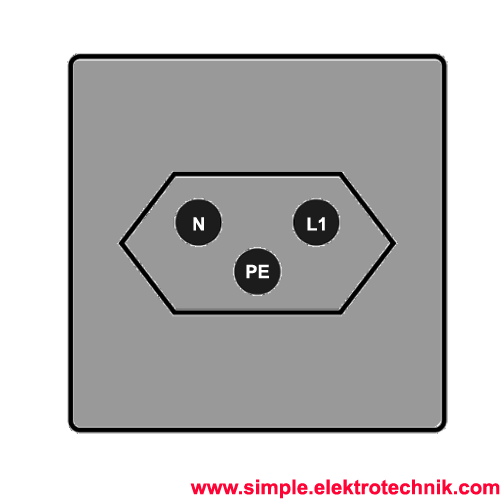
For Type 13 / Type 23 plugs, polarity is relevant. The plug has three pins: two flat parallel pins for the current and one round pin for grounding. The pins have different heights, so the plug can only fit into the socket in a specific way.
Usually, Type 13 / Type 23 plugs, sockets, or connectors have connections marked and labeled with (L) and (N) for live and neutral, and (PE) for protective earth (ground).
To enlarge the images, simply click on the images
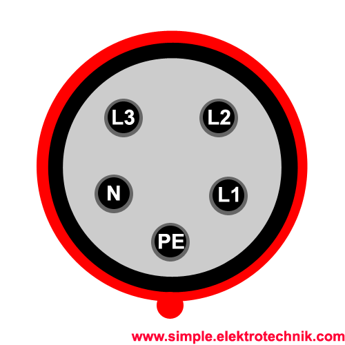
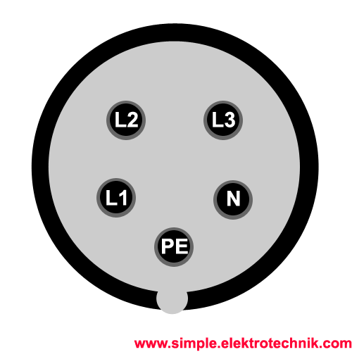
Polarity / Rotation Direction of Type 15 / Type 25 Plugs, Sockets, and Connectors
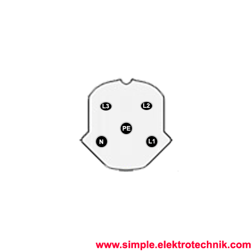
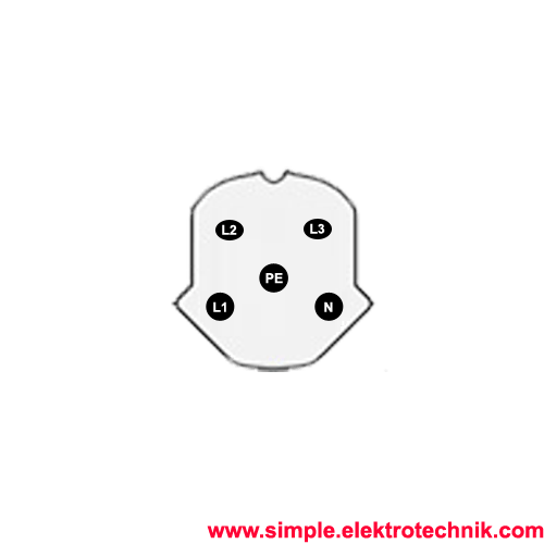
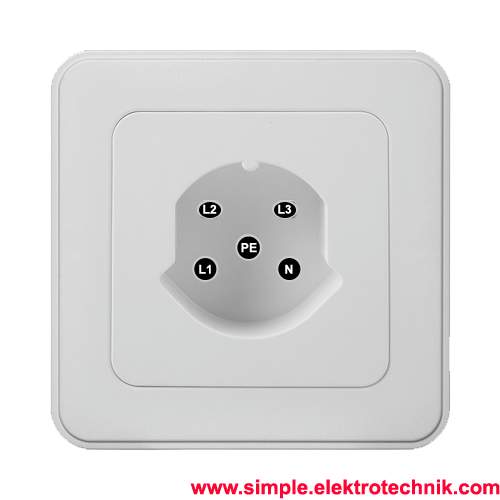
For Type 15 / Type 25 plugs, polarity is relevant. The plug has five pins: four flat pins for the current and one round pin for grounding. The pins have different heights, so the plug can only fit into the socket in a specific way.
Usually, Type 15 / Type 25 plugs, sockets, or connectors have connections marked and labeled with (L1), (L2), (L3), (N), and (PE) for live phases L1, L2, L3, neutral, and protective earth (ground), respectively.
To enlarge the images, simply click on the images
After connecting sockets, plugs, or connectors, it is absolutely crucial to check and measure the connections.
Before using the devices for the first time, you should verify the polarity of the socket/plug using a suitable measuring device. It is of the utmost importance to ensure that the protective earth (ground), the live phases, and the neutral are connected to the correct terminals to avoid serious faults.
Incorrect connections can lead to significant personal or property damage. Therefore, it is essential to ensure that the polarity is correct and that the sockets and connectors function properly to prevent potential risks.
Elektrosicherheit: Richtlinien und Vorsichtsmaßnahmen für einfache elektrotechnische Arbeiten
Die Sicherheit hat oberste Priorität.
- Alle hier bereitgestellten Anleitungen und Informationen dienen rein informativen Zwecken und sollen ausschließlich zur Informationsbeschaffung und Weiterbildung verwendet werden. Sie sollten nicht als Ersatz für professionelle Beratung angesehen werden. Bei Zweifeln empfiehlt es sich, einen qualifizierten Elektriker hinzuzuziehen, um fachkundige Unterstützung zu erhalten.
- Es ist wichtig, die örtlichen Vorschriften und Bestimmungen bei elektrischen Arbeiten zu beachten. Arbeiten mit Strom sollten nur von qualifizierten Fachleuten durchgeführt werden, da sie lebensgefährlich sein können.
- Fehler in Anleitungen und Schaltbildern sind möglich. Der Anbieter übernimmt keine Gewähr oder Haftung für Schäden oder Verletzungen, die aus der Umsetzung der bereitgestellten Informationen resultieren könnten. Es liegt in Ihrer Verantwortung, die Richtigkeit der Informationen zu überprüfen und die erforderlichen Sicherheitsvorkehrungen zu treffen.
- Die Verwendung geeigneter persönlicher Schutzausrüstung (PSA) ist entscheidend, um die Sicherheit bei elektrotechnischen Arbeiten zu gewährleisten. PSA schützt vor Stromschlägen, Augenverletzungen, thermischen und mechanischen Gefahren. Es ist jedoch wichtig zu beachten, dass PSA allein nicht ausreicht und durch Fachwissen, Fähigkeiten und die Einhaltung von Sicherheitsvorschriften ergänzt werden muss.
- Arbeiten an Teilen, die unter Spannung stehen, sind strengstens untersagt. Vor Beginn der Arbeiten müssen geeignete Sicherheitsvorkehrungen getroffen werden, einschließlich des Freischaltens der Anlage.
- Bei Schäden durch mangelhafte Elektroinstallation haftet der Errichter der Anlage gemäß den geltenden gesetzlichen Bestimmungen.
- Diese Zusammenfassung von Richtlinien und Vorsichtsmaßnahmen ist nicht umfassend. Bei Unsicherheiten ist es ratsam, einen qualifizierten Elektriker zu konsultieren oder sich an örtliche Vorschriften und Bestimmungen zu halten, um maximale Sicherheit zu gewährleisten.
- Die ordnungsgemäße Installation und Wartung von elektrischen Anlagen und Geräten ist von großer Bedeutung, um mögliche Gefahren zu minimieren und ein sicheres Umfeld zu schaffen.