TN, TT and IT earthing arrangements explained
The earthing arrangement describes how the source relates to earth and how the relevant exposed conductive parts are protectively connected. TN, TT and IT identify different arrangements.
Do not infer it from one core colour. It affects fault paths, protective measures and verification. These drawings are simplified functional illustrations, not wiring plans for an unknown installation.
Read the letters
The first letter describes the supply relationship to earth. T means direct connection of a point to earth. I indicates isolation of live parts from earth or connection through impedance.
The second letter concerns exposed conductive parts. T refers to their earthing through the relevant arrangement; N refers to protective connection to the earthed supply point.
Additional letters describe conductor functions. S separates protective and neutral functions; C combines them in PEN. These labels do not by themselves establish the actual design or acceptability of an existing connection.
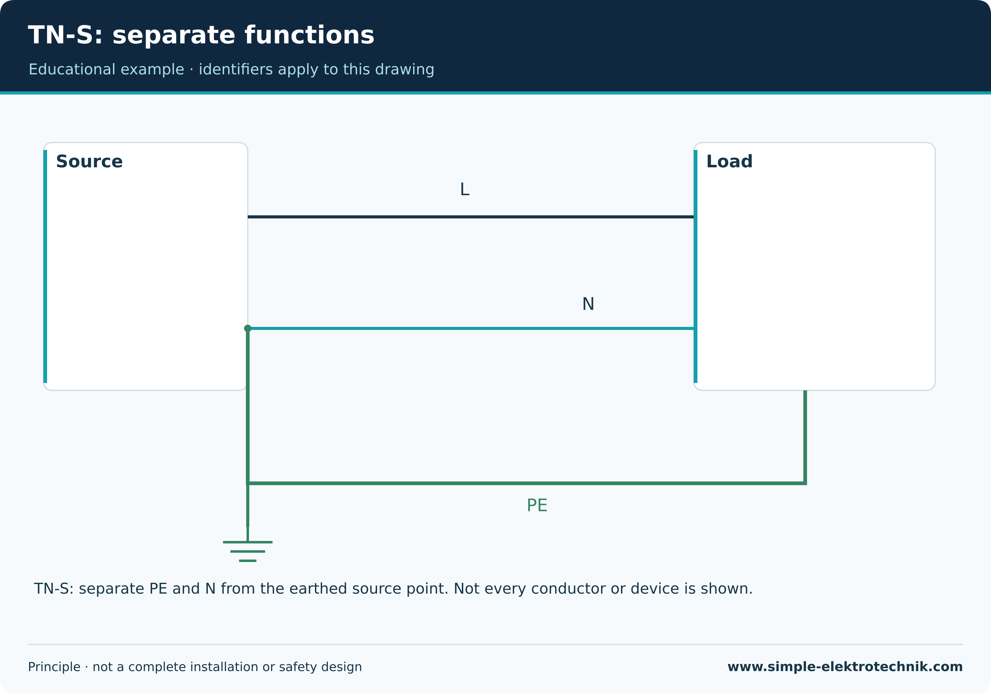
TN-S: separate PE and N
TN-S uses separate PE and N. PE connects designated enclosures to the earthed source point through the intended metallic path. Neutral belongs to the load-current system where needed.
An insulation fault can send current through PE back to the source. Intended protection must achieve the required effectiveness. The name TN-S alone does not prove this; design, construction and verification do.
TN-S: separate functions
TN-C and TN-C-S: consider PEN carefully
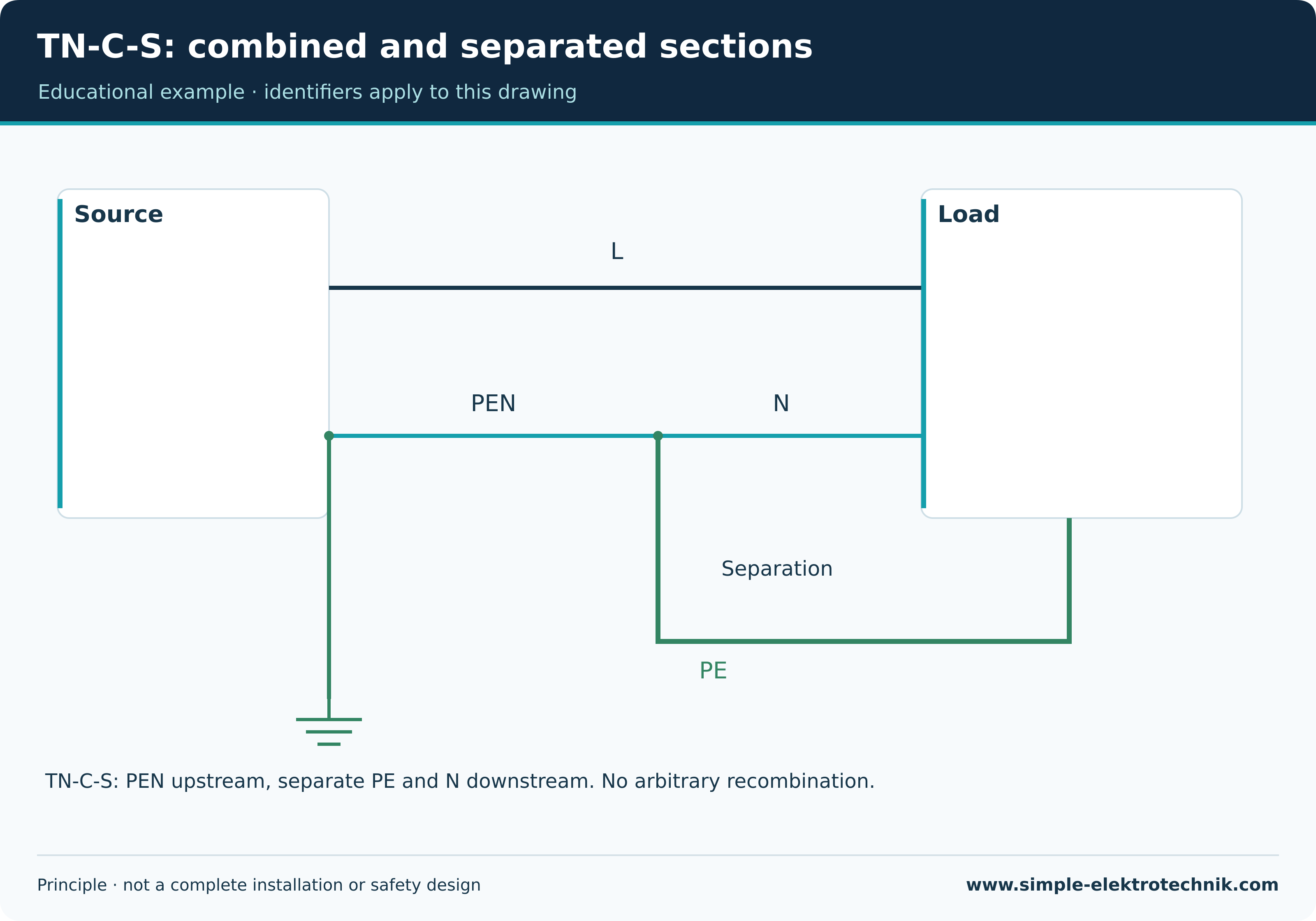
A TN-C section combines protective and neutral functions in PEN. TN-C-S has a combined section followed by separate PE and N. After the intended separation they are not arbitrarily recombined.
An interrupted PEN may impair protection and load return. An old socket bridge is not approved simply by calling it TN-C. Requirements and alterations need actual professional assessment.
TN-C-S: combined and separated sections
TT: include installation earthing
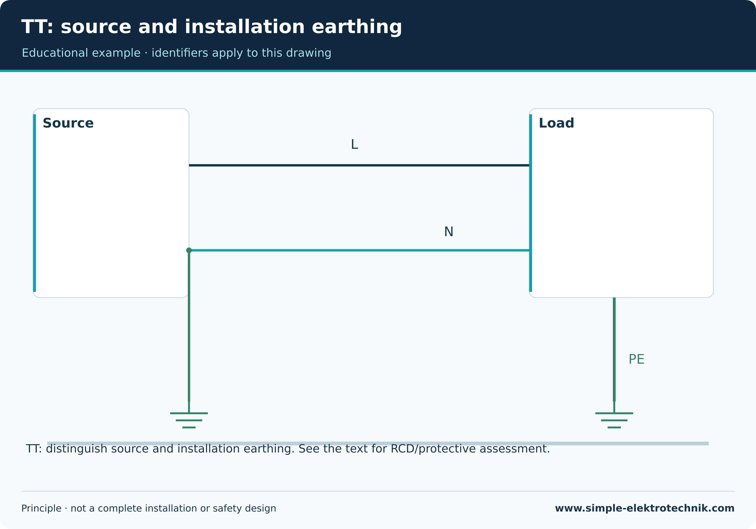
TT has an earthed supply point. Installation exposed conductive parts connect to the designated earthing arrangement. The relevant fault path includes that arrangement and soil.
Suitable RCD protection is important in usual TT concepts. Electrode resistance, protective connections and disconnection must be assessed together. Merely fitting an RCD does not certify complete effectiveness.
TT: source and installation earthing
IT: distinguish first and second faults
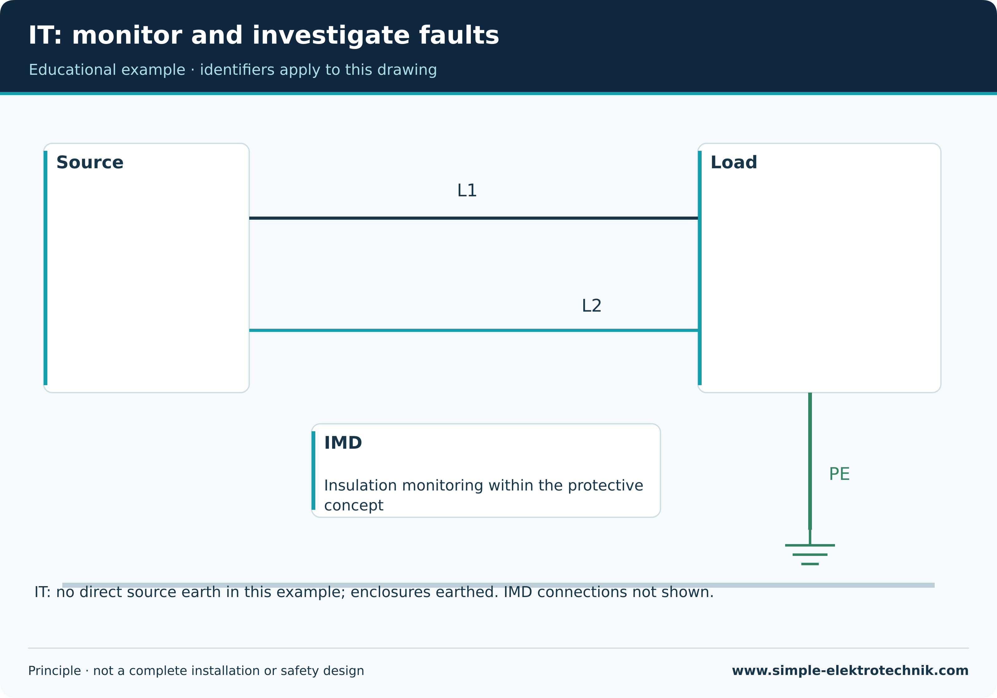
In IT, the source is isolated from earth or connected through suitable impedance. Exposed conductive parts still need earthing under the protective concept. IT does not mean no PE or no earth.
With suitable design, a first insulation fault can be indicated without immediate interruption, provided the necessary conditions are met. Insulation monitoring and prompt fault investigation form part of the concept.
A second fault can create hazardous paths requiring intended disconnection. Saying IT never disconnects would be wrong. Distributed capacitance, system extent and equipment affect behaviour.
IT: monitor and investigate faults
Comparison, not a ranking
| Arrangement | Characteristic | What it does not establish |
|---|---|---|
| TN-S | Separate PE and N | Automatic safety without verification |
| TN-C-S | PEN section followed by separation | Permission for arbitrary N–PE bridges |
| TT | Source and installation earthing | Electrode measurement replaces all other checks |
| IT | First-fault monitoring under suitable design | No PE or no eventual disconnection |
There is no best arrangement for every application. Supply, use, continuity requirements and protection determine design. Establish the actual arrangement from construction and documents rather than choosing it through an improvised alteration.
Consequences for testing
Loop impedance, electrode resistance, RCD testing and insulation monitoring answer different questions. Appropriate evidence depends on the protective concept. A TN calculation cannot automatically be transferred to TT or IT.
Alterations require assessment of common protective connections and the existing supply. The initial verification guide links this with individual methods. Austrian, German and Swiss provisions remain distinct; this guide deliberately gives no universal conductor sizes or disconnection limits.
Common questions
Can I identify the arrangement at a socket?
Not from superficial appearance or a simple tester alone. Reliable documents and professional investigation are needed.
Is TT just any additional earth connection?
No. Adding an earth does not automatically change the defined arrangement and protective concept of the whole system.
Does IT always mean harmless voltage?
No. Earthing arrangement and voltage magnitude are different properties. IT can also involve hazardous voltage.
Continue learning
Sources and technical context
The references support basic principles; they do not replace assessment of the actual installation.