Data outlets and structured network cabling
A data outlet terminates permanent network cabling in a room. It does not itself provide internet service. The outlet, patch panel, switch and router have different jobs; separating them helps both planning and fault finding.
This guide covers copper building cabling with the intended modular connections. Similar connector shapes do not make telephone and Ethernet services equivalent. The telephone guide covers analogue connections.
Router, switch, patch panel and outlet
A router connects networks and, depending on the setup, provides the route to the internet. A switch connects devices within the local network. A patch panel organises the fixed cable terminations; it does not actively switch data.
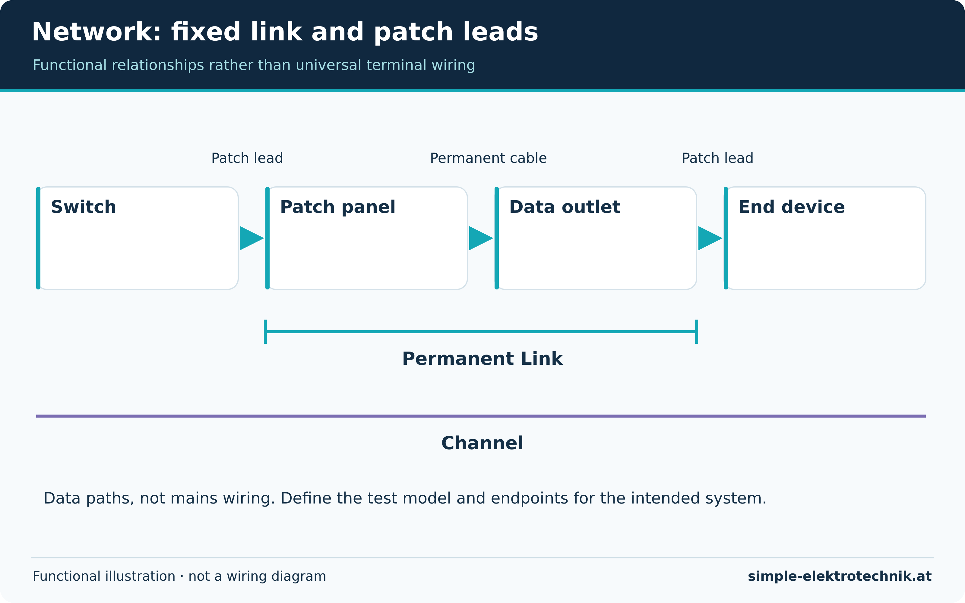
Permanent cable runs from the panel to the room outlet. Patch leads connect switch to panel and outlet to device. The principle illustration separates these sections. Its lines represent data paths, not mains wiring.
Verification distinguishes a Permanent Link from a complete Channel including its intended cords. Results and limits must match the link model actually tested. Without that definition, measurements are difficult to interpret.
Categories and performance
Component categories describe specified performance. The installed link depends on the coordinated system and its workmanship. A high-category cable alone cannot guarantee an equivalent completed link.
Outlets, panels, cords, length and termination all influence performance. Data rate also depends on active equipment and the transmission method. A higher number on a cable does not automatically make internet access faster.
Plan intended services and realistic expansion. Label both ends and document room and port allocation. Clear records often save more work than adding undocumented outlets.
Pairs and termination
Typical four-pair Ethernet cabling relies on defined conductor pairs. Follow the actual module's colour code and termination aids. T568A and T568B are not arbitrary patterns to mix; implement the intended scheme consistently.
Continuity of individual wires is not enough. A split pair can appear plausible in a basic continuity check while impairing transmission. Preserve pair structure and follow the manufacturer's preparation limits.
Bend radius, pulling force and tools depend on the cable and termination system. Avoid tight kinks and crushing fixings. Screening and bonding belong to the intended system; do not improvise a connection to any convenient earth point.
PoE and separation
Power over Ethernet supplies compatible devices through an intended data connection. Source, device, cabling and power demand must match. An arbitrary passive injector is not equivalent to negotiated standards-based PoE.
Cable bundles and higher power can require thermal assessment. Use the appropriate system documentation. A data connector is not a mains connection.
Power and data wiring require appropriate routing and separation for the system and local requirements. There is no single distance that applies to every cable, divider and environment.
Verification and fault finding
| Check | Scope and limitation |
|---|---|
| Inspection | Assess labels, damage and installation conditions. |
| Wire-map testing | Identify specified allocation, open-circuit and short-circuit faults. |
| Appropriate link measurement | Assess transmission performance against the defined link model. |
| Network operation | Check connectivity, negotiated speed and any PoE function. |
A link light or successful website request does not certify the cabling. Conversely, internet failure may originate at the router or service even when passive cabling is sound. Identify the affected section first.
A low negotiated speed can involve patch leads, damaged pairs, terminations or equipment capability. Substituting a known suitable patch lead can help isolate the cause. It does not replace required measurement of permanent cabling.
Common questions
Will a data outlet alone improve Wi-Fi?
No. It can provide a suitable wired connection for an access point. Radio performance still depends on placement, equipment and surroundings.
Is continuity on all eight wires sufficient?
No. Pair allocation and transmission performance can still be wrong.
Can a telephone outlet simply become Ethernet?
Only if the cable, topology and connections suit the intended network and are correctly converted and verified. Replacing the faceplate alone proves none of this.
Sources and documentation
More equipment guides: Equipment overview