Measuring and interpreting earth electrode resistance
Earth electrode resistance testing examines the connection between an earthing arrangement and the surrounding soil. It answers a different question from protective conductor continuity or fault loop impedance. Interpretation needs the electrode, method and protective measure.
Electrode resistance is expressed in ohms. Soil resistivity is a material property with a different unit. Confusing them can lead to incorrect assessment or method selection.
Identify the paths involved
Continuity testing concerns a defined conductive connection. Loop impedance includes a complete fault loop. Earth testing concerns the electrode or arrangement captured by the chosen method. Bonded electrodes, metal services and other parallel paths can influence the result.
One electrode is not the whole earthing installation. Connections, corrosion, mechanical condition and protective bonding also need attention. A low reading cannot justify visible damage.
Distinguish the methods
| Method | Principle | Conditions or limitations |
|---|---|---|
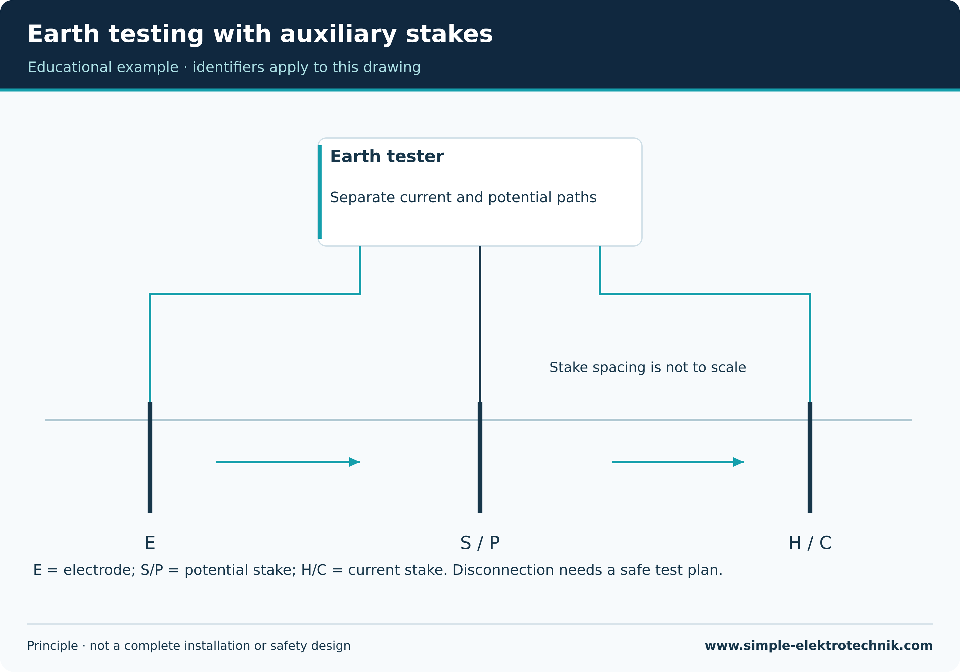
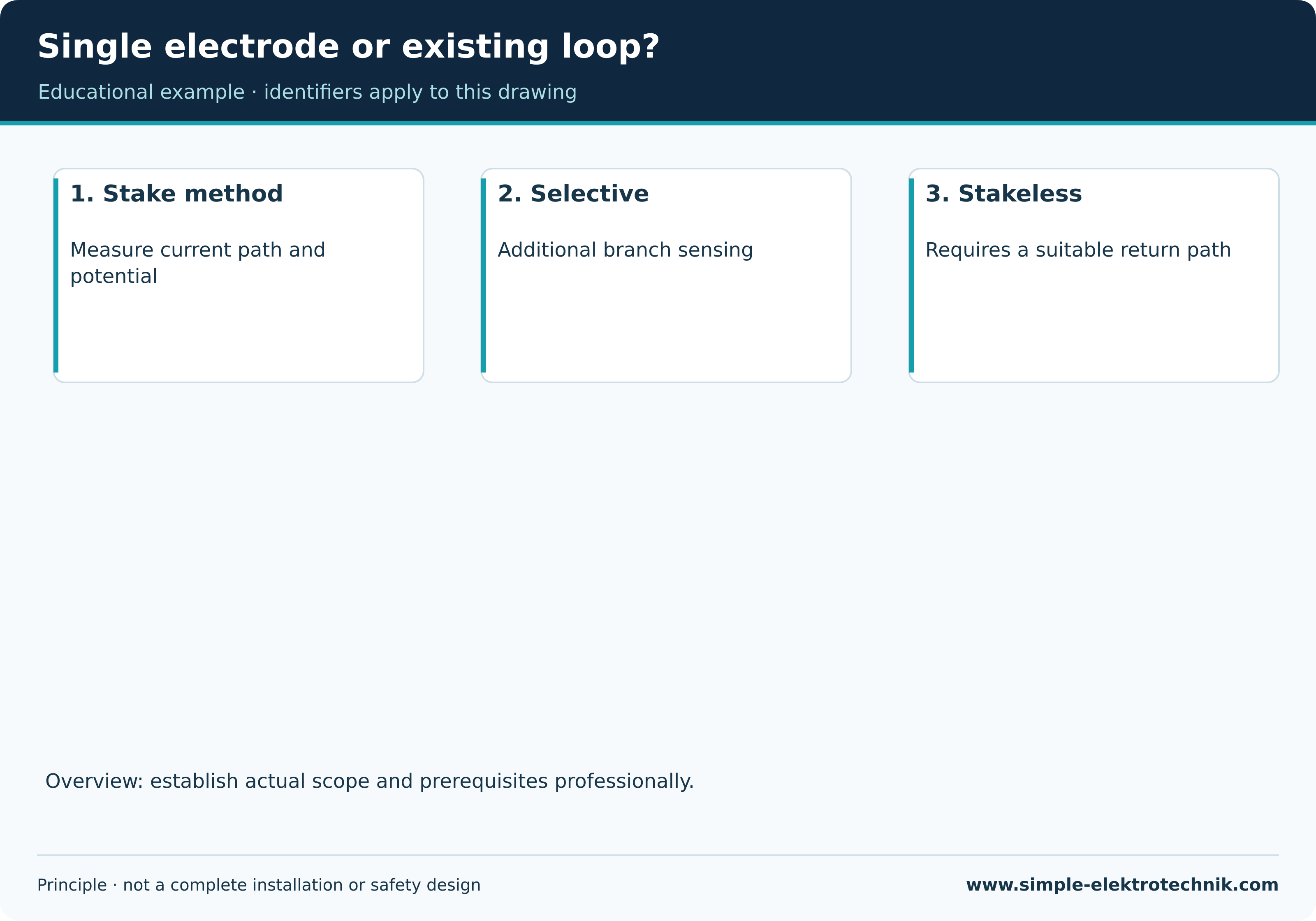
| Fall-of-potential test with auxiliary stakes | Test current flows between electrode and current stake; a potential stake samples voltage | Suitable positioning and separation of influence zones |
| Selective testing | Stake measurement with additional branch current sensing | Accessible conductor, suitable instrument and arrangement |
| Stakeless clamp method | Injected signal measures an existing loop | A suitable closed return path through other earths is necessary |
| Soil resistivity | Defined electrode arrangement investigates soil | Not a direct replacement for installed electrode resistance |
The illustrated stake arrangement is a principle drawing, not to scale. It gives no universal spacing. Electrode dimensions, soil and adjacent earths affect positioning. Result stability is checked under the chosen method.
Earth testing with auxiliary stakes
Why a clamp result can mislead
This clamp method requires a suitable closed measurement loop. It cannot arbitrarily determine an isolated electrode with no return path. The result concerns the loop actually captured and must not automatically be reported as the resistance of one electrode alone.
Selective measurement uses an additional current sensor to identify the branch contribution. Its instrument, stakes and model-specific conditions still matter. Possessing an ordinary current clamp does not establish this method.
Single electrode or existing loop?
Prepare safely
Identify the electrode and every relevant connection first. Disconnecting an electrode can impair protection; it is not a routine preparation step for an unqualified reader. The responsible professional determines whether disconnection is necessary and what safeguards are required.
Account for underground services before placing stakes. Suitable leads, protected work areas and instructions are part of the arrangement. Do not conceal interference or poor stake contacts by averaging arbitrary readings.
Assess the result
No single ohmic value automatically suits every earthing arrangement or country. Earthing system, protection, possible lightning protection and other requirements determine assessment. International manufacturer examples do not establish Austrian limits.
Moisture and season can alter readings. Comparisons need the earlier method and conditions. Record the electrode, connections, method, stake arrangement, result and assessment.
Common questions
Does this replace protective conductor testing?
No. A favourable connection to soil does not establish every protective conductor path inside an installation.
Can I use a multimeter instead?
Resistance between arbitrary metal parts is not equivalent to a defined earth testing method.
Related guides
Sources and technical context
Sources support this explanation. Public standard summaries do not replace the complete standard. Retain national context and equipment conditions.