

Ohm’s law explained

Ohm’s law describes proportionality between voltage and current in an ohmic resistor under unchanged conditions: U = R · I. It is useful but not a universal behavioural model for every electrical device.
We use clearly identified DC teaching examples. They explain relationships without presenting one simple equation as complete installation design.
Three forms of the equation
| Unknown | Equation | Inputs |
|---|---|---|
| Voltage | U = R · I | Resistance and current |
| Current | I = U / R | Voltage and resistance |
| Resistance | R = U / I | Voltage and non-zero current |
Units must be consistent. Volts and ohms give amperes. Convert a current stated in milliamperes appropriately; milli means one thousandth.
Example: calculate current
An idealised 120 Ω resistor has 12 V DC across it. I = 12 V / 120 Ω = 0.1 A, or 100 mA. Power is P = U · I = 1.2 W.
Power matters if the example becomes a real extra-low-voltage experiment. Resistance may be correct while the component is thermally unsuitable. Actual selection requires its rating and conditions.
Changing resistance and voltage

At constant 12 V, increasing resistance to 240 Ω reduces current to 0.05 A. Keeping 120 Ω but reducing voltage to 6 V also gives 0.05 A. The same current may therefore come from different combinations.
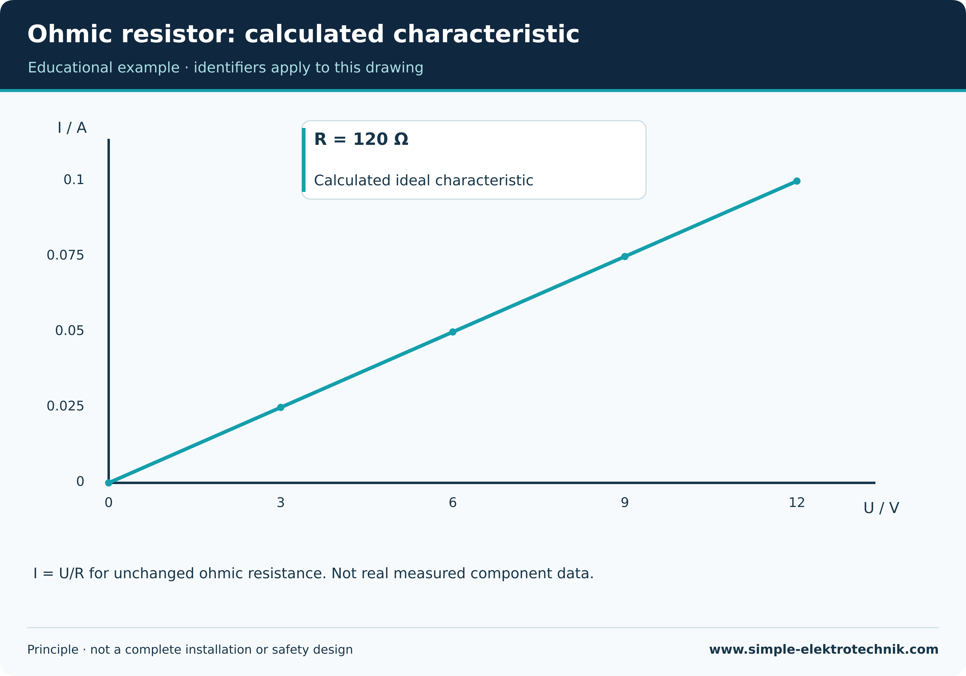
An ideal ohmic characteristic is a straight line through the origin with the appropriate axes. The illustration contains calculated values, not real component measurements.
Ohmic resistor: calculated characteristic
Series and parallel
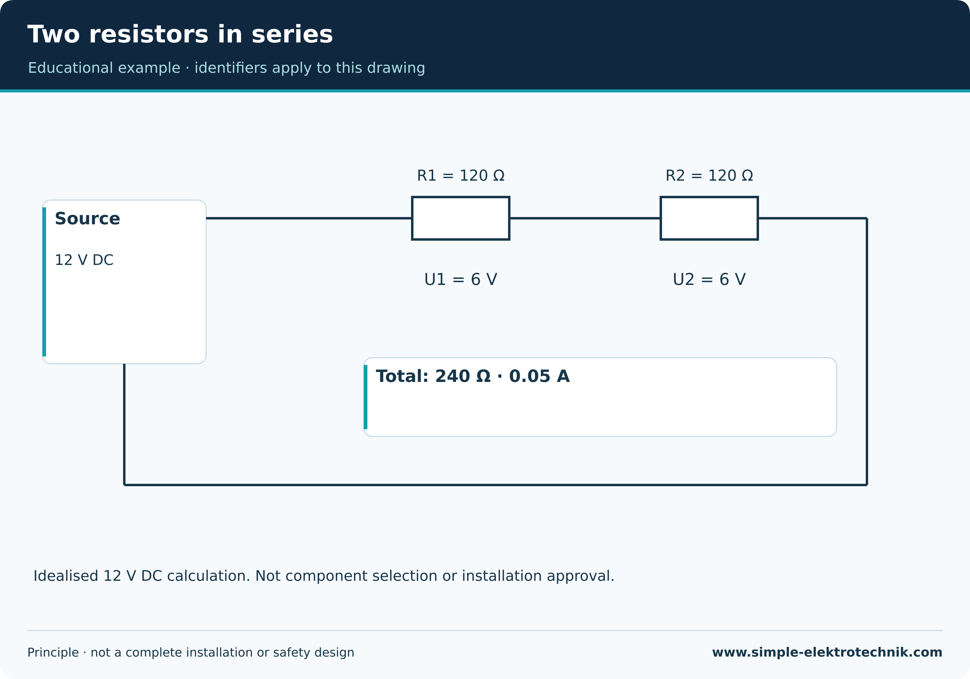
Two series resistors carry the same current. Their resistances add and the total voltage divides. Two 120 Ω resistors in series across 12 V carry 0.05 A, with 6 V across each.
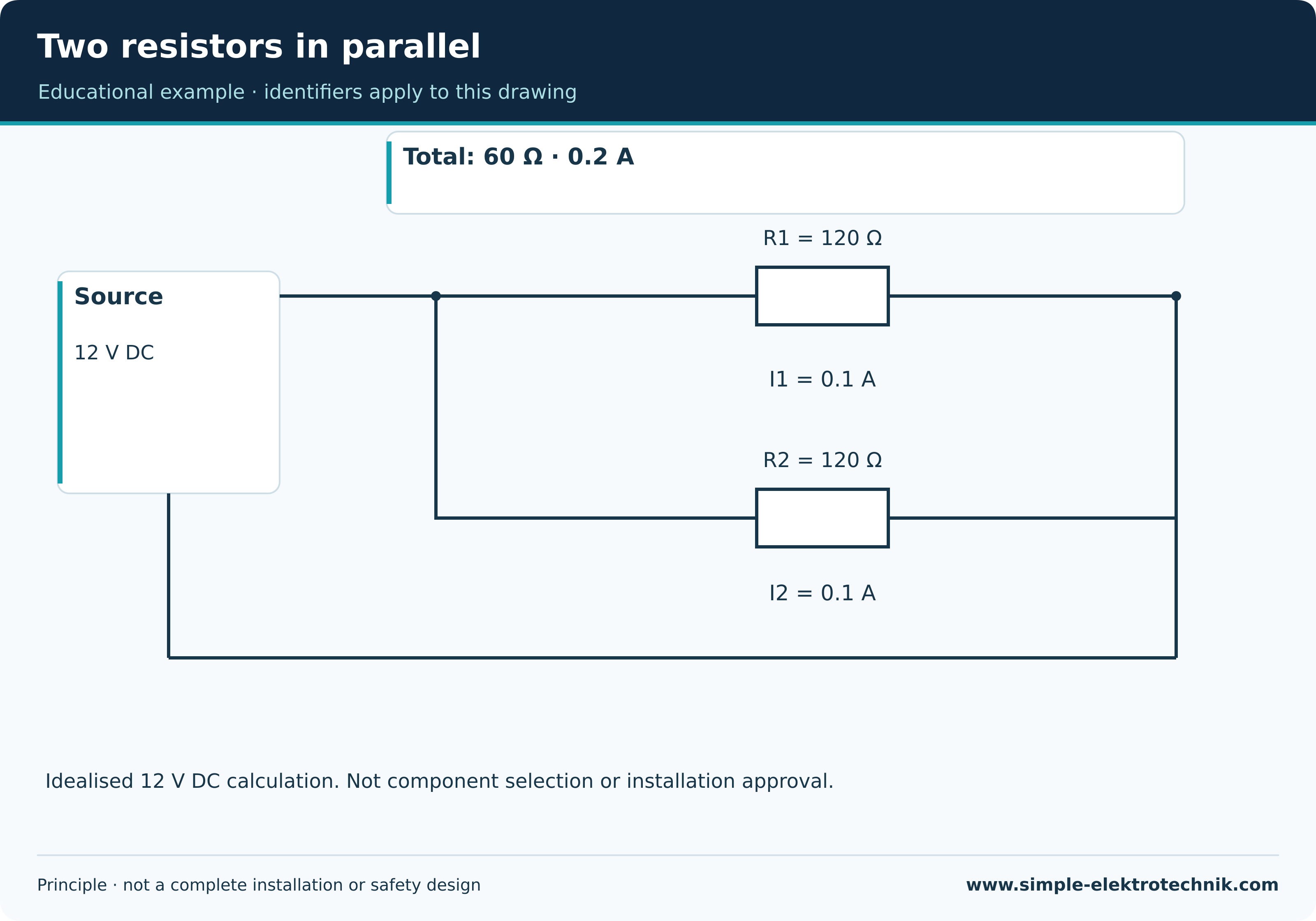
Two parallel 120 Ω resistors each receive the same voltage. At 12 V each branch carries 0.1 A and total current is 0.2 A. Equivalent resistance is 60 Ω. The source must supply the total current.
These statements concern the defined ideal model. The German installation term Serienschalter describes a type of lighting switch; it does not mean the lamps are necessarily connected electrically in series.
Two resistors in series
Two resistors in parallel
Limits of the simple model
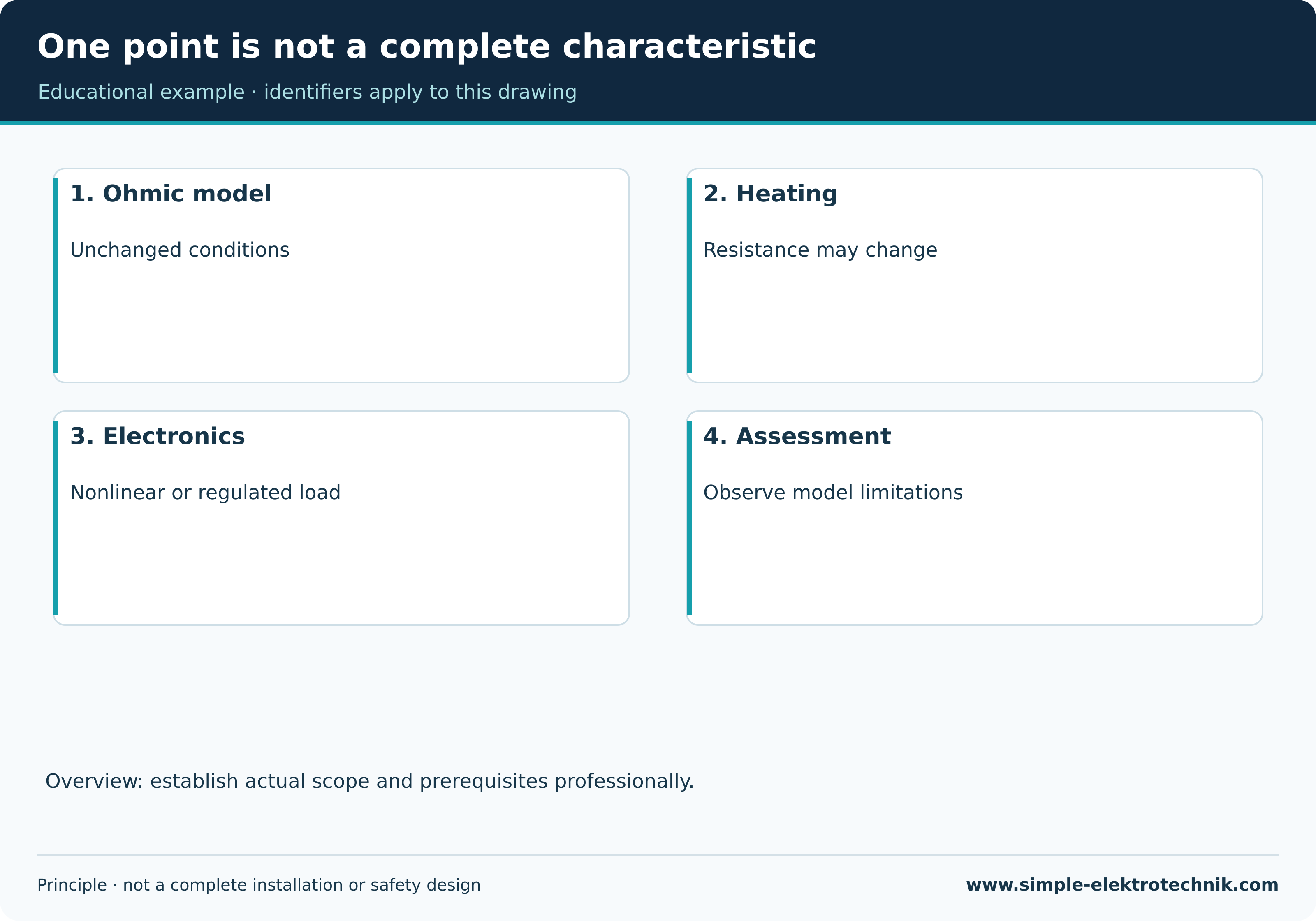
An incandescent filament changes resistance as it warms. A diode has a nonlinear characteristic. Regulated electronics may adjust current consumption. A U/I ratio at one operating point does not establish constant resistance at other voltages.
Impedance matters for AC circuits containing reactive effects. The simple constant DC resistance model does not capture all those relationships. A human body is likewise not an unchanging classroom resistor from which safe contact can be calculated.
One point is not a complete characteristic
Common calculation errors
Retain the units: 100 mA is not 100 A. A short circuit is not a normal use of an ideal source with zero resistance. Actual sources, conductors and protection determine the possible current.
Check plausibility. At unchanged voltage, increasing an ohmic resistance cannot increase current. Such questions expose mistakes early.
Common questions
Is R = U/I always the same as Ohm’s law?
The ratio describes an operating point. Ohm’s law additionally describes proportional behaviour under the relevant unchanged conditions.
Can this equation alone select cable size?
No. Capacity, installation conditions, protection, voltage drop and other requirements form part of the design. One favourable calculation cannot replace them.
Continue learning
Sources and technical context
The references support basic principles; they do not replace assessment of the actual installation.