

Common measurement errors and systematic diagnosis

An unusual reading is an observation, not a diagnosis. The cause may be in the installation or in the settings, points and identification. Systematic investigation separates these possibilities without defeating protection.
Immediate component replacement or selecting only favourable readings can hide the real fault. Start with the test question and actual arrangement.
Understand the result first

Record what was expected and what was displayed, including units, range and messages. An over-range indication does not mean the same as a specific finite resistance.
Verify the object and location. Incorrect labels or a shared neutral may invalidate the initial assumption. Further comparisons are weak without reliable identification.
| Observation | Possibilities to investigate |
|---|---|
| Unusually high continuity reading | Contact, lead compensation, route or poor connection |
| Unexpectedly favourable continuity | Parallel path or wrong measurement points |
| Low insulation resistance | Loads, electronics, moisture, contamination or damaged insulation |
| Unexpected RCD operation | Existing leakage, method, incorrect attribution or actual defect |
| Voltage changes with the instrument | Input impedance, coupling, reference point or load-dependent fault |
| Implausible phase sequence | Connections, missing conductor or incorrect interpretation |
These are possible investigation routes, not proof that one observation has one particular cause.
Check the instrument and arrangement
Damaged leads, incompletely closed clamp jaws or wrong zero compensation can distort results. Appropriate functional comparison helps isolate instrument problems. Follow instructions and maintain safe conditions.
A high-impedance voltage input can show coupled voltage. Suitable further investigation may explain its behaviour. Do not dismiss an indication as harmless based on a guess. The voltage guide explains the limitations.
Narrow the area systematically

Divide a known system into traceable areas using permitted procedures. Consider loads, sections and junctions. Record every temporary change so the correct final state can be restored.
Insulation testing of a smaller section may show where a concern remains. Required conductors and protective measures must not be disconnected indiscriminately. A favourable reading on one isolated part says nothing about the excluded remainder.
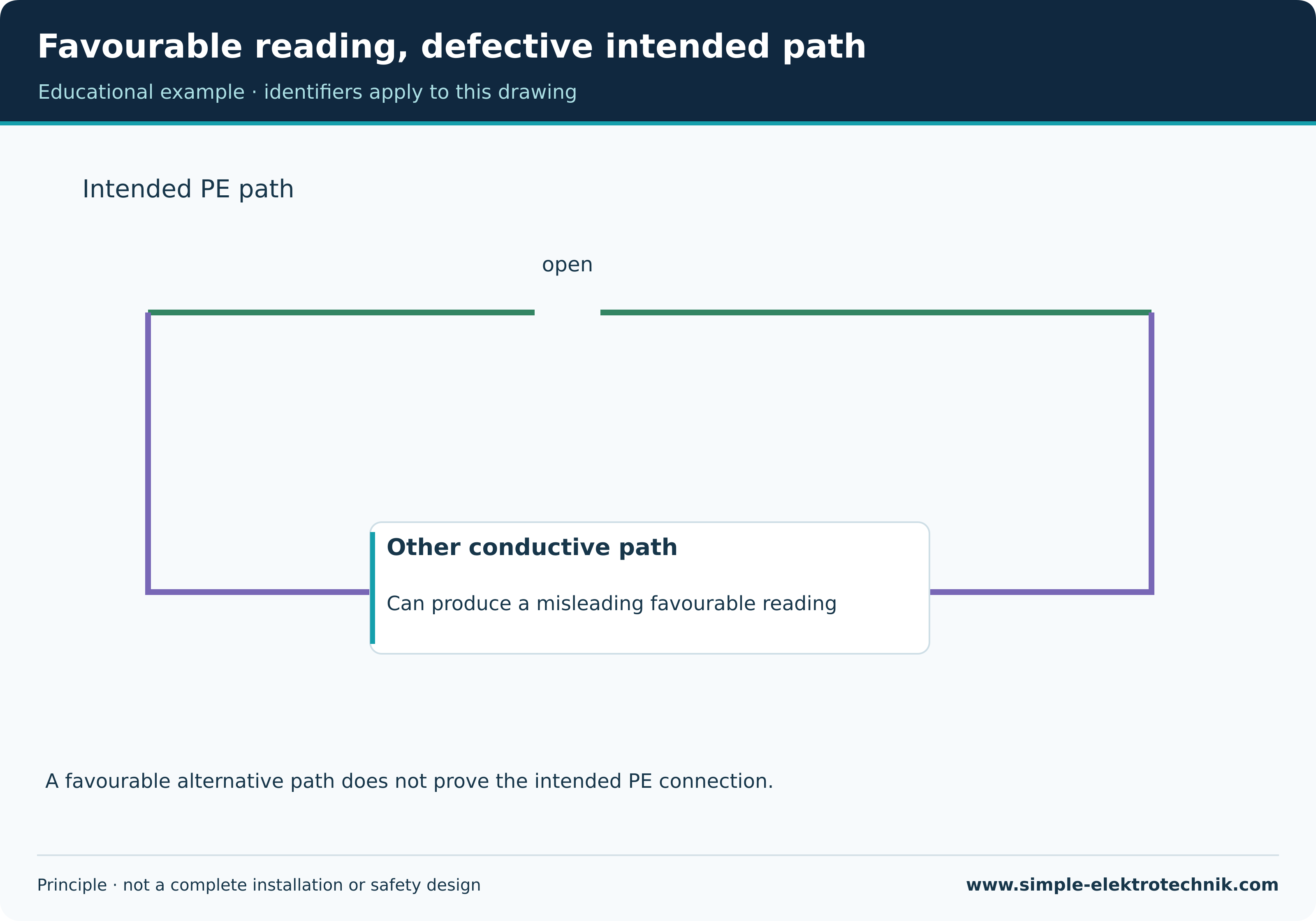
Example: low resistance despite an interrupted PE
Other equipment or conductive building parts can create a parallel path. A low reading may then appear despite a defective intended conductor. Installation knowledge, inspection and appropriate measurement belong together.
Do not investigate by removing protective connections experimentally in service. The responsible professional defines safe checks. Only evidence of the intended path answers the original question.
Favourable reading, defective intended path
Retest after correction
A repair can affect previously verified parts. Determine the necessary repeated electrical and functional checks after restoration. A working load alone does not complete the diagnosis.
Record the original observation, confirmed cause, correction and retest separately. If unresolved, state that explicitly. “Did not recur during this visit” does not prove elimination.
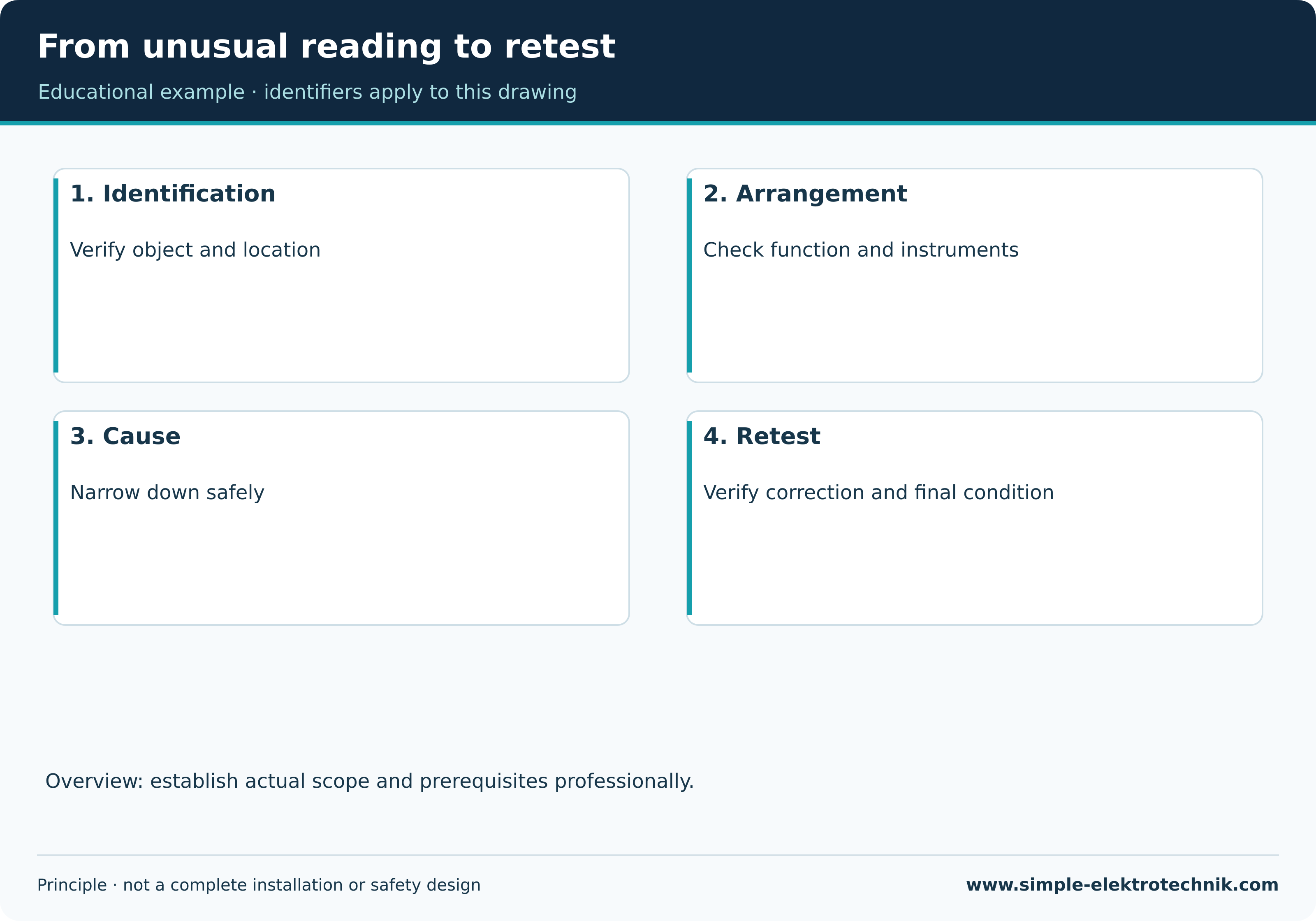
From unusual reading to retest
Common questions
Should I repeat until a result passes?
No. Repetition needs a technical purpose and comparable conditions. Variability is itself information to investigate.
Can an automatic programme identify the cause?
It can provide clues and messages. It does not automatically know the entire installation or every possible cause.
Related guides
Sources and technical context
- Fluke 1672/1673 FC/1674 FC – Users Manual, Rev.4,06/2026
- Megger DCM305E – Earth leakage clampmeter
- Megger – How insulation resistance is measured
Sources support this explanation. Public standard summaries do not replace the complete standard. Retain national context and equipment conditions.