

Electrical quantities and fundamentals

Voltage, current and energy are easily confused in everyday discussion. Here you can find each term’s role, units and simple examples. Distinguishing the quantities helps interpret equipment specifications and basic circuit diagrams.
Formula conditions are explained alongside them. An ideal DC example is not complete design for an unknown installation. The links lead to the fundamentals guides for a fuller explanation.

How these terms connect
Voltage, current, power and relationships within a circuit. The short definition supports quick lookup. Open an entry for its example, important distinctions and useful references. Related terms link to further entries in the glossary.
The linked guides explain applications in greater detail. This glossary explains terminology and replaces neither product documentation nor assessment of an actual installation.
Look up a term
23 terms found
A
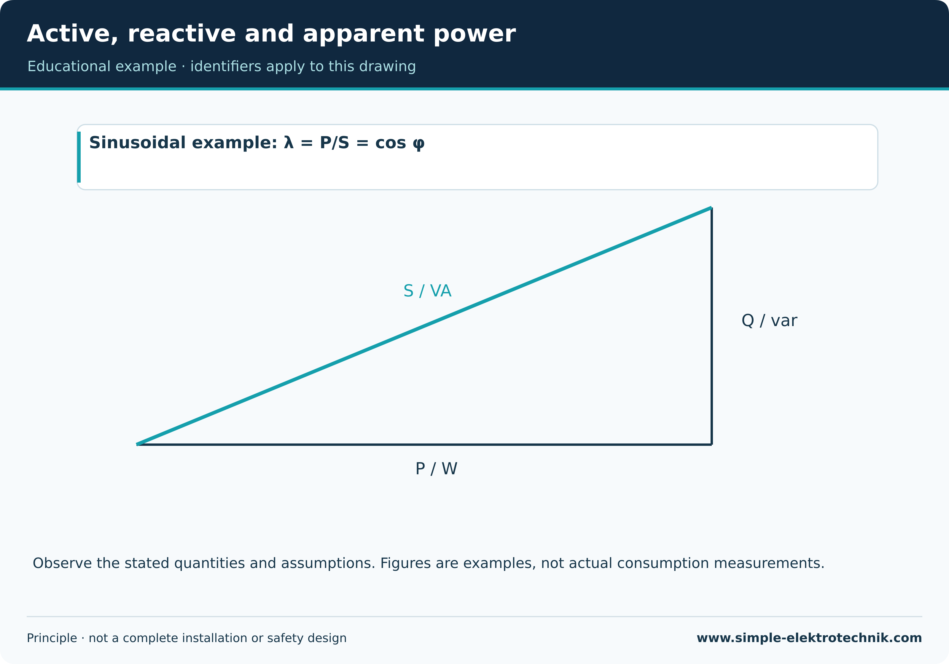
Active, reactive and apparent powerActive power is the average rate of energy conversion. Apparent power is the product of RMS voltage and current; reactive power describes the corresponding exchange component in the sinusoidal case.
The quantities are expressed in W, VA and var. For sinusoidal waveforms, their relationship can be shown in a power triangle. For distorted waveforms, that simple picture does not cover every power decomposition.
Example
An inductive load may require more current for the same active power than a load with a power factor close to one.
Important distinction
Reactive power is not itself an efficiency loss. The associated current can nevertheless increase loading of conductors and equipment.
Alternating currentAlternating current changes direction. A sinusoid is an important waveform, but not the only possible one.
Sinusoidal voltage is commonly specified by its RMS value. The relationship between RMS and peak depends on waveform. For a sine wave, the factor is √2.
Example
230 V RMS for an ideal sine wave corresponds mathematically to a peak of about 325 V.
Important distinction
A zero crossing does not permit contact. A changing waveform does not replace safe isolation and verification of absence of voltage.
D
Direct currentDirect current maintains the same direction. Its magnitude need not be constant in every case.
An ideal DC voltage source has fixed polarity and constant voltage. Real sources can vary; a pulsating rectified current is therefore distinct from ideal constant DC.
Example
A battery supplies suitable equipment with a defined polarity. Electronics may produce other voltages from it.
Important distinction
An AC contact rating is not automatically a DC approval. Low DC voltage is not harmless regardless of source and environment.
E
EfficiencyEfficiency describes the ratio of useful output power to input power.
The difference may appear as heat or other real losses. What counts as useful output must match the equipment and the specified operating point.
Example
A motor can absorb electrical power and deliver a smaller mechanical power at its shaft.
Important distinction
Efficiency, power factor and a product energy class are not interchangeable specifications. Efficiency also often changes with load.
Electric chargeElectric charge is a physical quantity describing electrical interactions. Its unit is the coulomb.
Current describes how much charge passes a point per unit time. For constant current, the charge transferred is Q = I · t. Charge and electrical energy are different quantities.
Example
A constant current of 1 A transfers 1 C of charge in one second.
Important distinction
Q is also used for reactive power in another context. The unit and context therefore need to be considered.
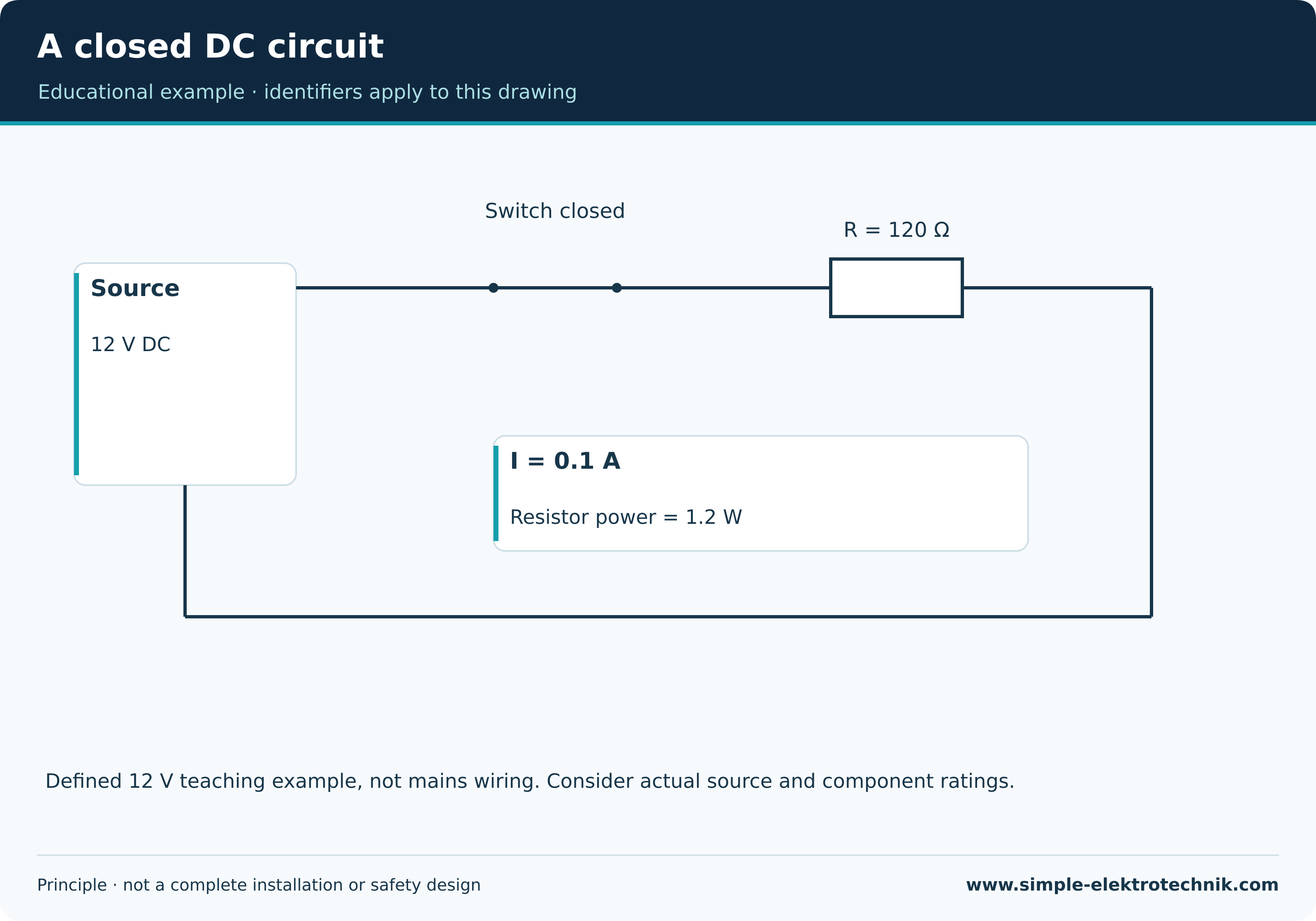
Electric circuitAn electric circuit is an arrangement of connections and components. A closed conducting path allows steady current from a suitable source.
A simple DC circuit has a source, outward path, load and return path. Actual installations may have branches, protective devices and additional sources.
Example
An open switch can interrupt load current while voltage remains across its contacts.
Important distinction
A circuit is not safe merely because a load does not work. Faults and alternative supplies require separate consideration.
Electric currentElectric current describes the rate of transport of electric charge. Its unit is the ampere.
Conventional current follows the direction of positive charge movement. In metals, electrons move in the opposite direction. A load does not simply use up charge.
Example
In an unbranched series circuit, the same current passes through each component if no additional branches exist.
Important distinction
Amperes do not express an amount of energy. The danger of a current depends on factors including its path, duration and contact conditions.
EnergyElectrical energy describes the amount of energy transferred or converted. Common units are the joule and kilowatt-hour.
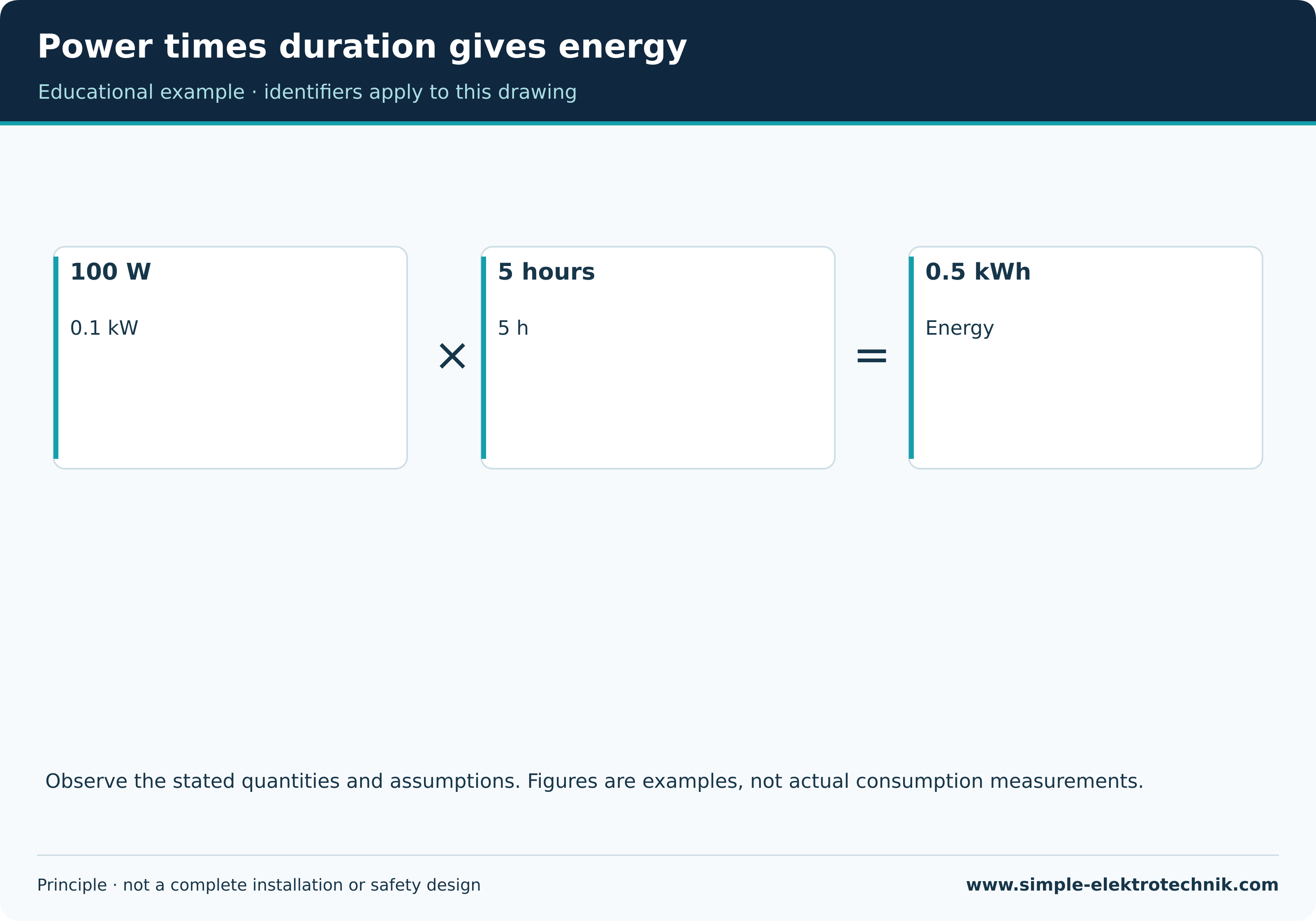
For constant power, E = P · t. With varying power, its time history is taken into account. A kilowatt-hour combines power and operating time; it is not a type of electric current.
Example
100 W for five hours gives 0.1 kW × 5 h = 0.5 kWh.
Important distinction
A power-supply rating does not automatically describe its continuous energy consumption. Load, losses and operating duration matter.
F
FrequencyFrequency is the number of periods of a periodic process per unit time. Its unit is the hertz.
For a sine wave, one period includes a complete positive and negative cycle. Period T and frequency are related by f = 1/T.
Example
A hypothetical 50 Hz oscillation repeats every 0.02 s. This illustrates the relationship mathematically.
Important distinction
Frequency is not voltage magnitude. The same RMS voltage at a different frequency can still impose different equipment conditions.
I
ImpedanceFor sinusoidal AC quantities, impedance is the complex ratio of voltage to current. Its unit is the ohm.
It includes resistive and reactive components and their phase relationship. Frequency and operating conditions may affect its value.
Example
A real path with inductive properties can behave differently under AC from a simple DC assessment.
Important distinction
Impedance and ohmic resistance are not universally interchangeable. A magnitude without frequency and context does not describe every property.
K
Kirchhoff’s lawsKirchhoff’s laws describe fundamental relationships between node currents and loop voltages in a suitable circuit model.
The signed current sum at a node is zero. Around a closed loop, the algebraic voltage sum is also zero in the appropriate model. Reference directions and signs must be consistent.
Example
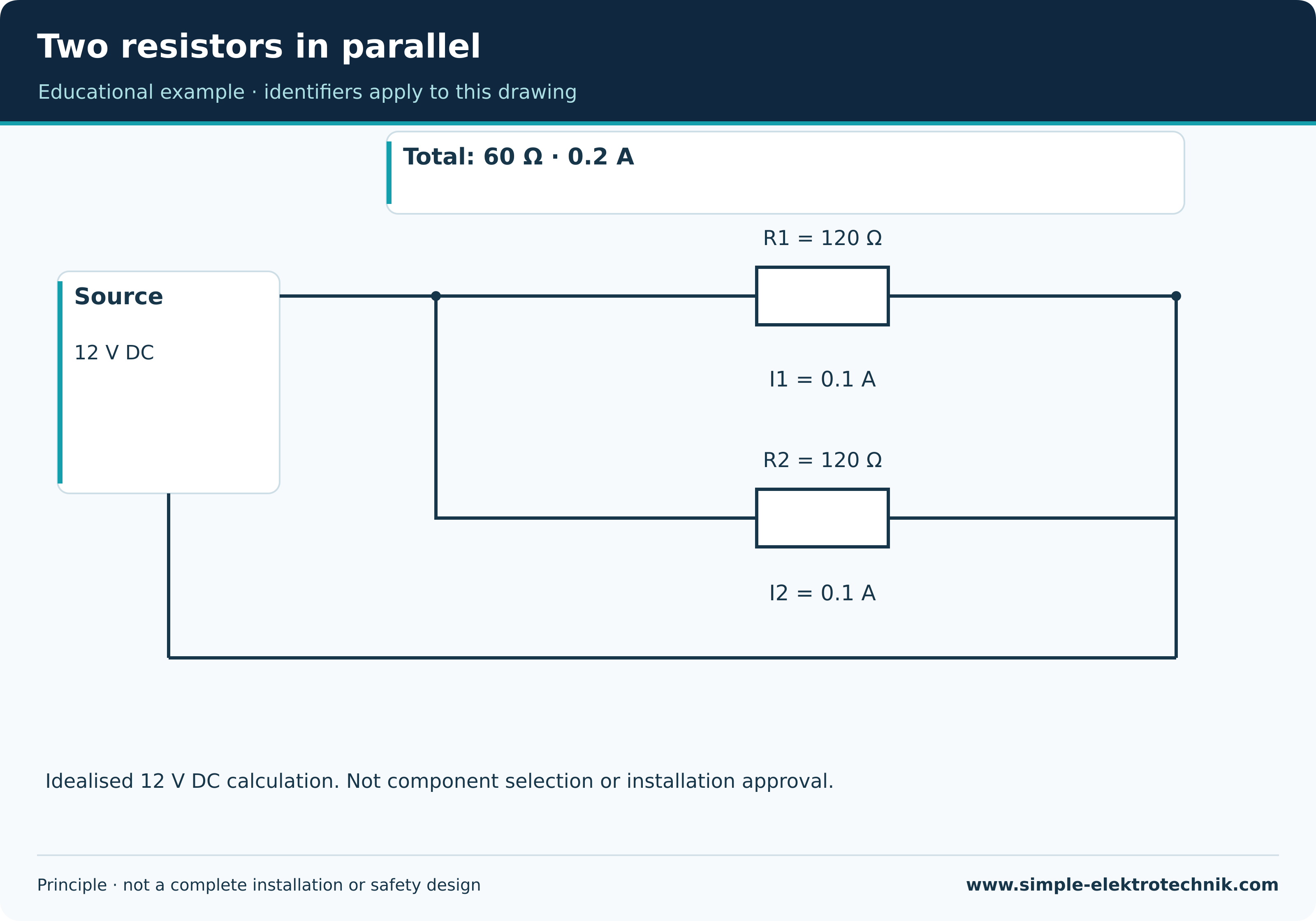
If 0.2 A divides into two equal branches, each carries 0.1 A in the ideal example.
Important distinction
Circuit analysis can require component models and additional relationships. A simple DC model does not automatically describe all electromagnetic behaviour.
O
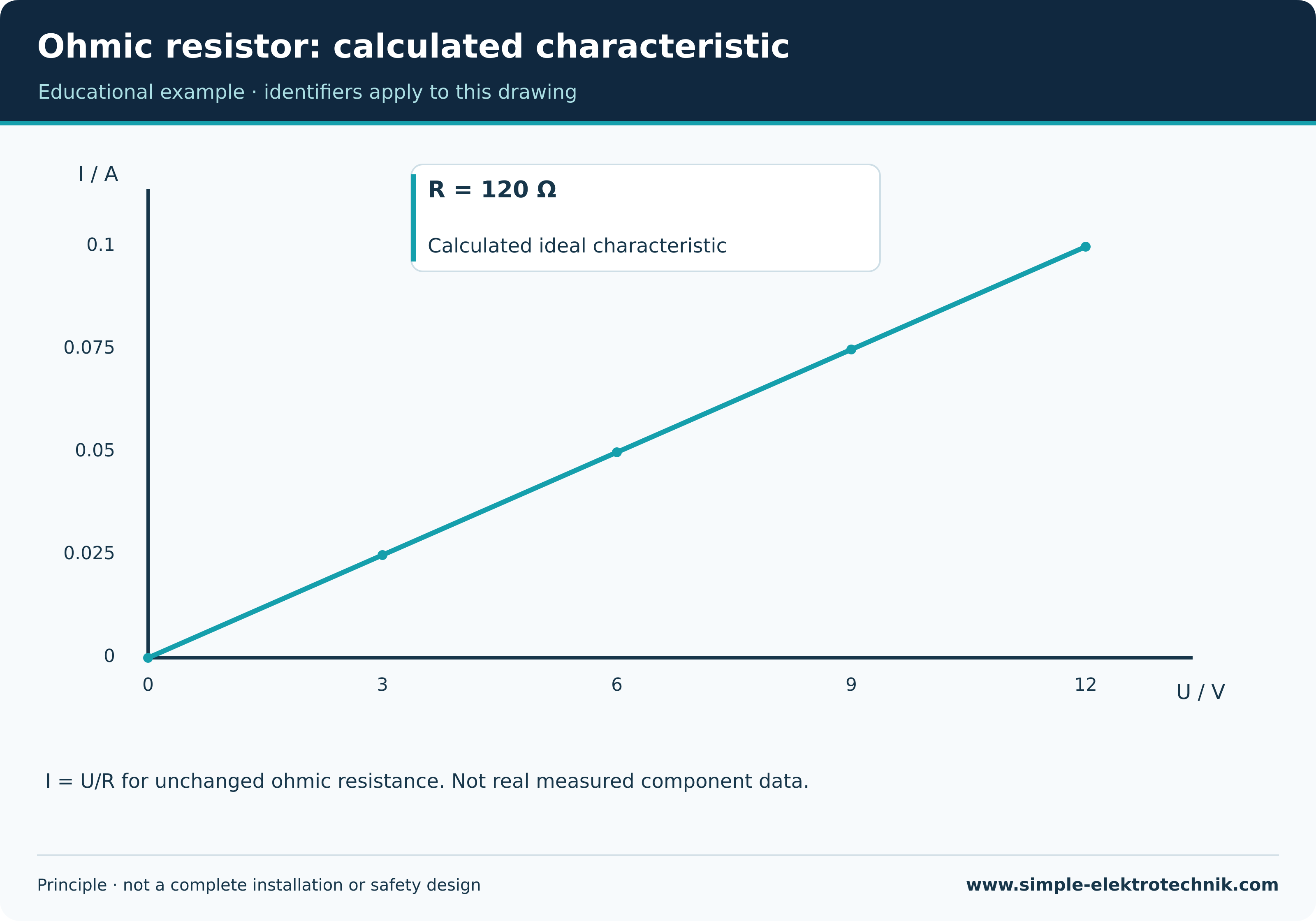
Ohm’s lawOhm’s law describes proportionality between voltage and current in an ohmic resistor under unchanged conditions.
The relationship U = R · I can be rearranged for the required quantity. It describes a suitable model and is not a complete design rule for electrical installations.
Example
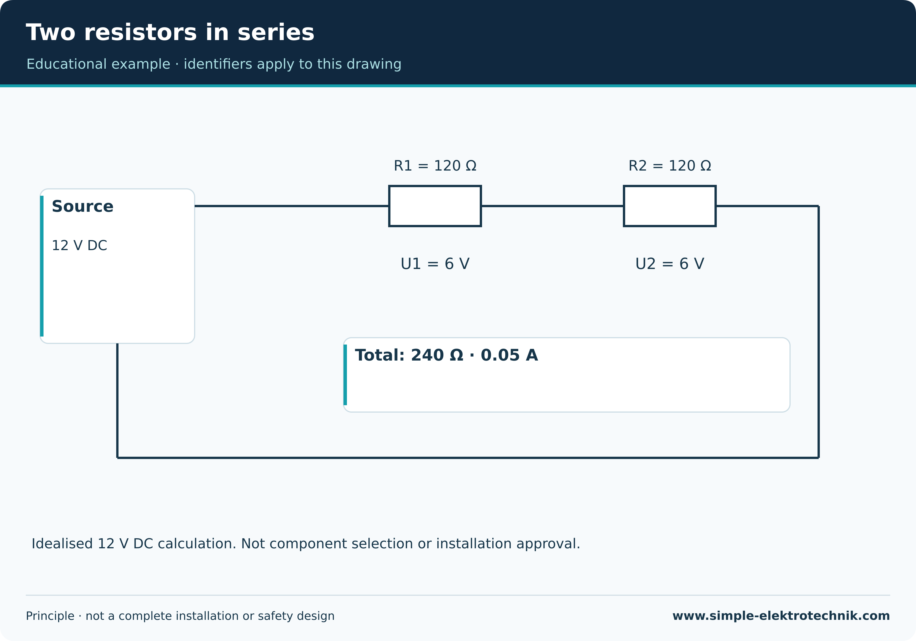
Two 120 Ω resistors in series give 240 Ω. Across 12 V, this idealised example carries 0.05 A.
Important distinction
One U/I ratio does not establish ohmic behaviour over a wider range. An incandescent lamp changes resistance as it heats.
OverloadAn overload occurs when an otherwise intact circuit or item of equipment is loaded beyond its permitted conditions.
Excessive current can cause unacceptable heating over time. Permissible loading depends on construction, environment and operating conditions.
Example
Several simultaneous loads may overload an extension lead without a short circuit being present.
Important distinction
A protective device needs suitable selection. A higher current rating does not fix insufficient conductor capacity.
P
Parallel connectionIn a parallel connection, multiple branches are connected across the same two nodes. Those branches have the same voltage.
Total current is made up of the branch currents. For ideal resistors, equivalent resistance is lower than the smallest individual branch resistance.
Example
Two 120 Ω resistors in parallel across 12 V each carry 0.1 A; the source supplies 0.2 A in total.
Important distinction
Connecting arbitrary sources in parallel is not a general application of this rule. Sources must be suitable and properly coordinated.
Phase displacementPhase displacement describes the relative timing of periodic quantities. It is often expressed as an angle.
At the same frequency, a time shift can be related to one complete period. In sinusoidal AC, current may for example be displaced relative to voltage.
Example
An ideal resistive load has sinusoidal voltage and current in phase. Ideal reactive elements behave differently.
Important distinction
The everyday use of phase to mean a line conductor is different. Phase displacement is not a measured proof of installation safety.
PowerPower describes the rate at which energy is transferred or converted. Its unit is the watt.
Instantaneous power is p(t) = u(t) · i(t). For DC quantities, P = U · I can be used. Power control adjusts delivered or absorbed power through a suitable method.
Example
A lamp operating at a constant 100 W uses 0.5 kWh of electrical energy in five hours.
Important distinction
Watts are not an amount of consumption. AC requires distinctions between active, reactive and apparent power; U · I is not always active power.
Power and low-current systemsPower and low-current systems are broad terms whose meanings depend on technical and legal context.
Everyday usage often distinguishes energy supply from information transmission. This is not a universal voltage boundary or a statement of permission to perform work.
Example
A data cable carries information; suitable systems may also supply device power over it.
Important distinction
Low-current does not automatically mean safe to touch or fire-safe. Voltage, available energy and actual protective measures matter.
Power factorPower factor is the ratio of active power P to apparent power S. It is often denoted by λ.
Only for sinusoidal waveforms does the magnitude of power factor equal the magnitude of cos φ. Nonlinear loads may also distort current, making that simple equivalence unsuitable.
Example
An LED supply may draw a different current waveform from an ideal resistor. Its technical documentation therefore matters.
Important distinction
A high power factor does not establish high efficiency. The two specifications describe different properties.
R
ResistanceElectrical resistance describes the relationship between voltage and current for a component. It is expressed in ohms.
For an ohmic resistor under unchanged conditions, U = R · I. For other components, the ratio U/I may depend on operating point and temperature.
Example
At 12 V across a constant resistance of 120 Ω, the calculated current is 0.1 A.
Important distinction
A body, LED or regulated power supply is not an arbitrary fixed classroom resistor. Reactive effects may also matter in an AC circuit.
S
Series connectionIn an unbranched series connection, the same current passes through components connected one after another.
The individual signed voltages make up the total voltage. For ideal resistors, resistance values add. Voltage divides according to those resistances.
Example
Two equal resistors across a total of 12 V each have a 6 V voltage drop in the idealised case.
Important distinction
A German Serienschalter does not imply that its lamps are electrically in series. Distinguish the device name from the circuit principle.
Short circuitA short circuit connects points intended to remain separated through a relatively low impedance.
Possible current is limited by the source, conductors and complete fault path. Suitable protective devices must match the installation and prospective fault current.
Example
Damaged insulation can allow an unintended connection between live conductors.
Important distinction
A short circuit is not an ordinary overload. A fault between two live conductors is not detected by every residual-current-only device.
Short-circuit currentShort-circuit current is the current in a considered short circuit. Prospective short-circuit current describes the expected value under defined conditions.
Source impedance, conductor path and fault type influence it. Protective assessment includes disconnection behaviour and suitable breaking capacity.
Example
Different points within one installation can have different prospective short-circuit currents.
Important distinction
A value derived from a measurement is not a deliberately created real short circuit. Method and uncertainty form part of its assessment.
V
VoltageVoltage is the electrical potential difference between two points. Its unit is the volt, and U is commonly used as the quantity symbol.
A voltage always refers to two points. A battery can have voltage across its terminals even when no load is connected and no steady load current flows.
Example
Across an idealised 120 Ω resistor, 12 V DC produces a current of 0.1 A.
Important distinction
Voltage and current are different quantities. An off load or an interrupted circuit does not prove absence of voltage.
No matching term. Try another spelling or select all topics.