

Measuring current, residual current and leakage

Current measurement may investigate load current or small currents flowing on unintended paths. The conductors inside the clamp determine the question. Different positions can yield different information, provided the instrument is suitable.
Load current, residual current and protective conductor current are not interchangeable. None alone replaces an RCD test or insulation resistance test.
Three different arrangements

| Arrangement | Quantity investigated | Important limitation |
|---|---|---|
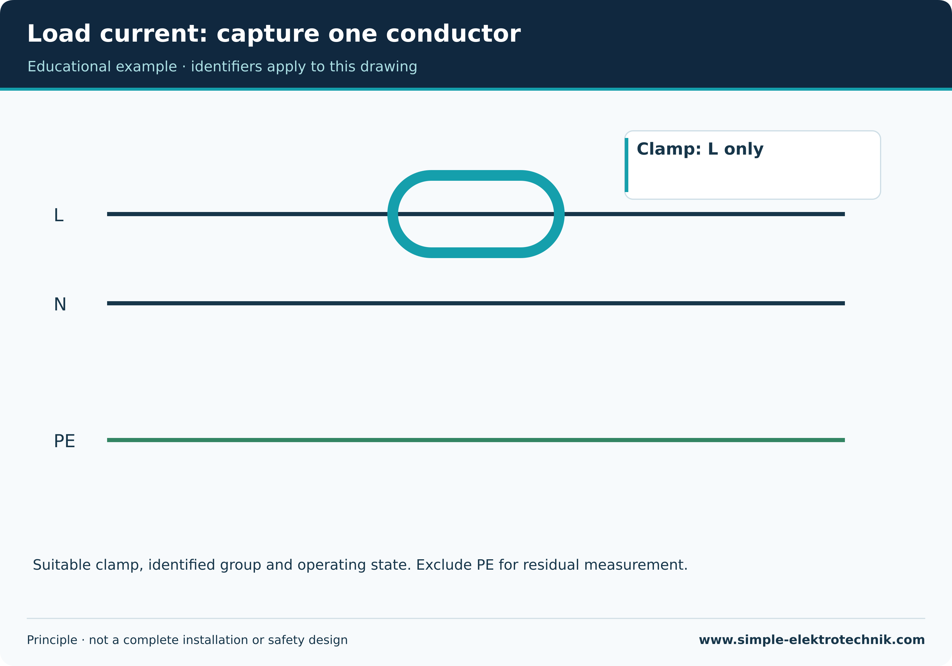
| Suitable clamp around one live conductor | Current in that conductor | Multiple conductors can produce cancelling magnetic effects |
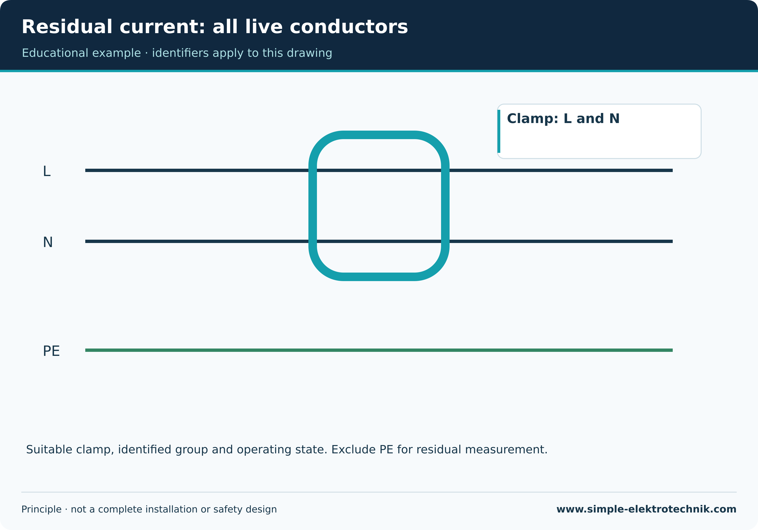
| Suitable clamp around every live conductor of one circuit, excluding PE | Resultant current sum or residual current | Other return paths and unrelated conductors affect attribution |
| Suitable clamp around the protective conductor | Current in that protective path | Other leakage paths are not fully captured |
For a single-phase circuit, residual measurement includes L and N together. A suitable three-phase arrangement includes all its live conductors and neutral where present. PE remains outside. This is a principle, not an instruction to open a live board.
Clamping the complete flexible cable including PE can capture a different quantity. It is not automatically equivalent to residual current measurement excluding the protective conductor.
Load current: capture one conductor
Leakage does not always mean a defect
Filters and capacitance may produce operational leakage in intact equipment. An unexpectedly high result nevertheless needs explanation. Multiple loads, their filters and operating states may contribute.
Terminology also depends on the method. Protective conductor current is the current in that path under the selected conditions. Touch current requires an appropriate measuring network; an arbitrary clamp arrangement cannot replace it.
Residual current: all live conductors
Select suitable equipment

A coarse ordinary current clamp may miss small leakage. Range, resolution and frequency response must suit the task. An AC clamp does not automatically measure smooth DC. True RMS is valid only within its specification.
Jaws need to be clean and fully closed. Position, nearby conductors and any zero adjustment can affect results. Filters may suppress disturbance while excluding relevant frequency components. Record the setting.
Operating state matters
Standby can differ from heating, motor operation or switching on. One stable reading may not explain intermittent trips. Suitable recording or targeted investigation may be required.
Diagnosis divides the installation into known areas using appropriate safe methods. Never remove a protective conductor to prevent tripping. Nor can the troublesome operating state simply be excluded and the installation declared satisfactory.
Assess and record
Record the conductor group, location, instrument, range, filter, operating state and result. Establish that the current belongs to the circuit under consideration. Shared neutrals or unintended return paths require investigation.
Limits depend on the object and method. Preset clamp comparison values are not universal RCD limits. Residual current alone does not establish the current and time at which an RCD will operate.
Common questions
Why does a clamp around L and N show nearly zero?
Equal outward and return currents largely cancel magnetically. Measure one suitable conductor for load current; use the complete live group for residual current.
Does low leakage prove good insulation?
Not completely. Operating leakage and insulation resistance tests use different conditions and answer different questions.
Related guides
Sources and technical context
Sources support this explanation. Public standard summaries do not replace the complete standard. Retain national context and equipment conditions.