

Initial verification before putting an installation into service

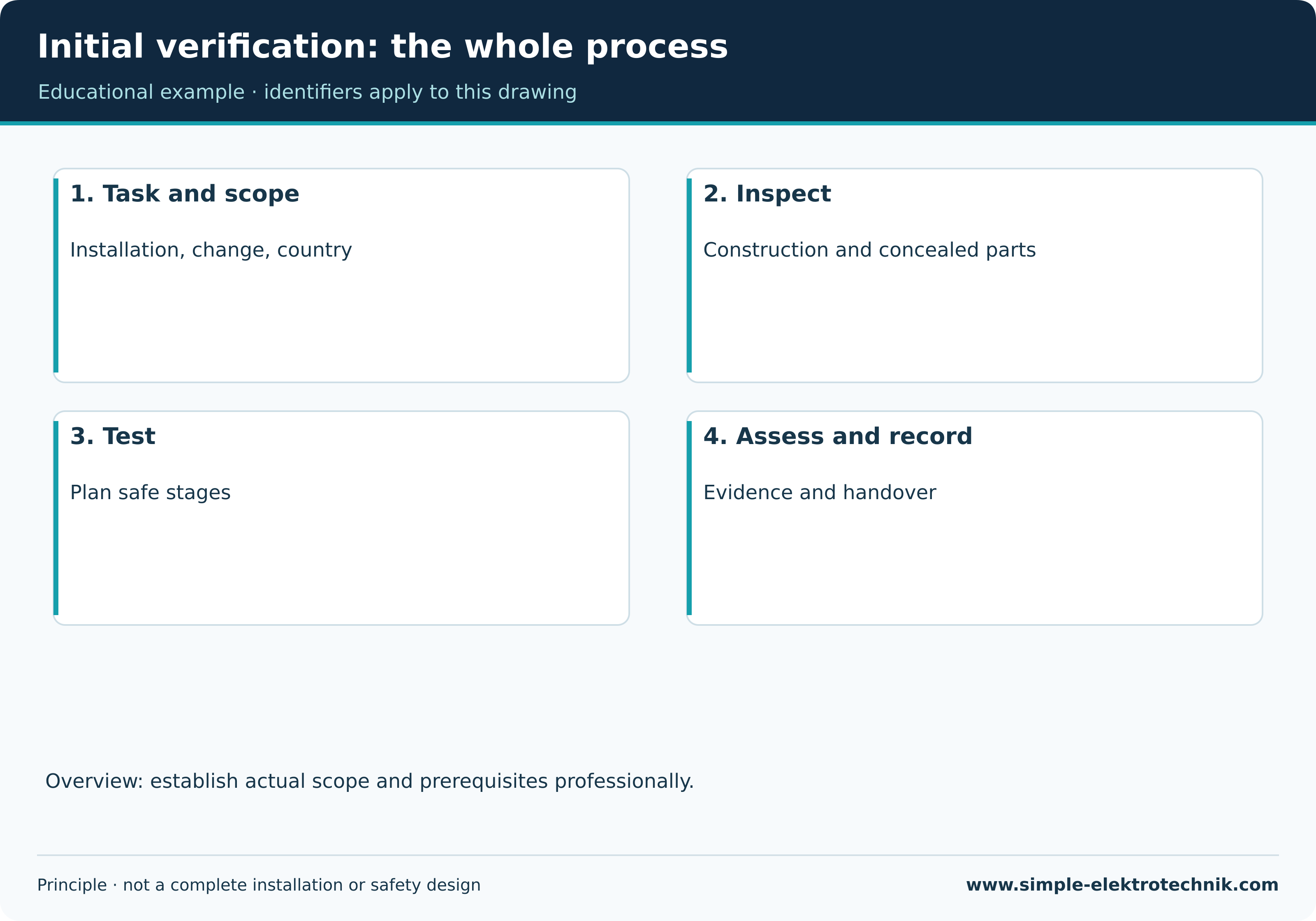
Initial verification establishes whether a new or altered electrical installation meets the applicable requirements and can be put into service safely. It combines inspection, testing, evaluation and records. Switching on and finding that the lights work is not enough.
Verification starts during construction, not only after the last cover has been fitted. Connections and routes that will become concealed need attention while accessible. Some tests require the installation to be safely isolated; others need a supply. A suitable plan connects these stages without exposing people or equipment to unnecessary risks.
This guide concerns ordinary low-voltage installations. PV systems, charging equipment, medical locations and machinery can need additional verification. The educational examples below are not a universal release checklist.
Initial verification, commissioning and periodic inspection

Initial verification forms part of completing an installation or verifying an alteration. Commissioning brings it into its intended operation. Periodic verification assesses an installation already in service. Their scope and supporting records can differ.
Repair can also require testing. Whether work constitutes a significant alteration, extension or repair under particular rules cannot be decided from its price or duration alone. The work, its consequences and the applicable framework matter.
| Situation | What the verification plan needs to address |
|---|---|
| New distribution board and final circuits | The complete new installation, supply, protective measures and records |
| Additional circuit from an existing board | New circuit and suitability of affected existing supply and protective measures |
| Extension of an existing circuit | New equipment, changed routes and affected shared parts |
| Replacement of damaged equipment | Selection, connection and verification required after the intervention |
| Unaltered installation after use | Reason for and scope of periodic or condition assessment |
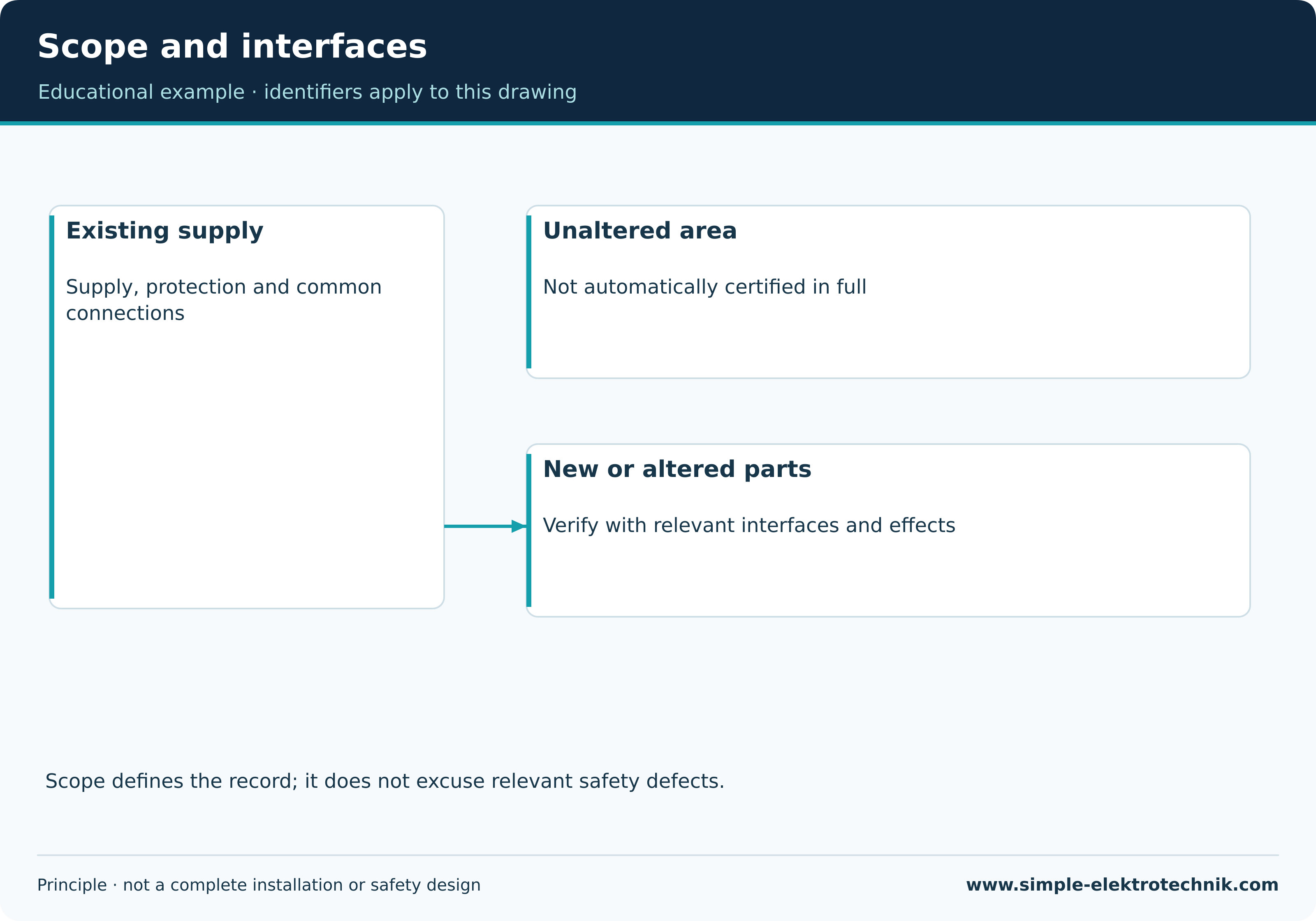
An additional circuit does not automatically mean every untouched part of the building has been certified. Conversely, an inadequate common protective conductor cannot be ignored because it lies outside the newly installed cable.
Initial verification: the whole process
Austria, Germany and Switzerland: keep the context clear
In Austria, OVE E 8101 addresses the erection and verification of low-voltage installations. Public OVE information identifies the 2025 edition. Specific methods, exceptions and assessment conditions must come from the applicable requirements and accessible technical documentation. A public summary does not replace the complete standard.
Within Austrian occupational safety, section 8 of ESV 2012 addresses verification before putting installations into service after erection or re-erection and after significant alterations, significant extensions or repair. That legal reference has its own scope, including workplaces and construction sites. It does not establish one inspection interval for all private homes.
For Germany, DKE's public summary of DIN VDE 0100-600 describes initial verification through inspection and testing following new work, extensions or alterations. German national provisions are not automatically Austrian requirements.
In Switzerland, ESTI distinguishes recorded initial verification during construction before putting the installation into service from the final inspection before handover. A required independent acceptance inspection is a further separate activity. Responsibilities, records and exceptions follow NIV and the relevant provisions. These are not interchangeable names for one task.
This English article retains those national contexts. It does not turn them into a UK or US inspection procedure.
Define the scope and prepare the information

Identify what will be verified: for example new board DB1 and its circuits, or the extension of circuit Q3. Clear identifiers prevent a result later being attached to the wrong socket or protective device.
Prepare current drawings, circuit schedules, earthing arrangement information, conductor details, protective device data and equipment instructions. Operational needs matter too: which loads must stop, which controls retain settings and who may restore each supply?
Other sources must be identified. PV, batteries, UPS equipment, standby supplies and separately supplied control circuits can change the situation. Opening one circuit-breaker does not by itself establish that every affected conductor is dead.
A suitable instrument must support the required methods. Test leads, adapters, measurement category, voltage limits and accessory condition are part of suitability. Functional checks and any lead compensation follow the instructions. A stored correction needs reconsideration when the test lead arrangement changes.
Scope and interfaces
Inspection: more than a quick look
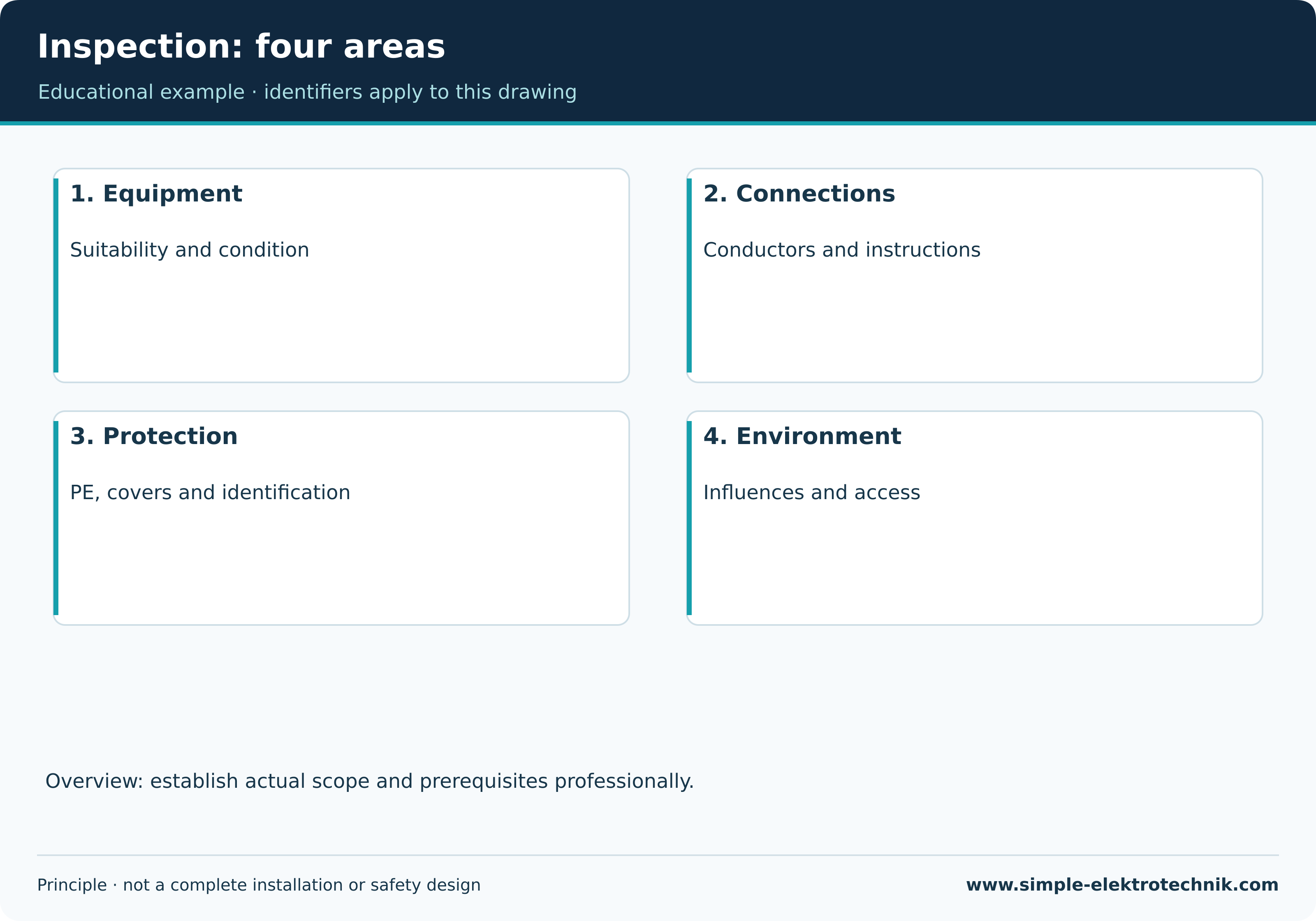
Visual inspection accompanies construction. Connections that will become inaccessible are checked while they can still be examined. Completion inspection includes covers, identification and restored connections.
Typical points include suitable equipment selection, intact insulation, protection against contact, conductor identification and traceable protective conductor connections. Entries, strain relief, permitted terminal occupancy and manufacturer requirements for conductors also matter.
A favourable reading does not exclude every defective connection. An unsuitable terminal or damaged enclosure does not become acceptable because the tester displays a green tick.
The visual inspection guide explains these checks in more detail. Pictures illustrate points of attention; they cannot certify an installation from its appearance alone.
Inspection: four areas
Tests in the isolated state
A safe condition is established and verified for the relevant work and tests. The five safety rules are applied as appropriate to the installation and task. This must be distinguished from the later controlled supply needed for particular tests.
Protective conductor continuity
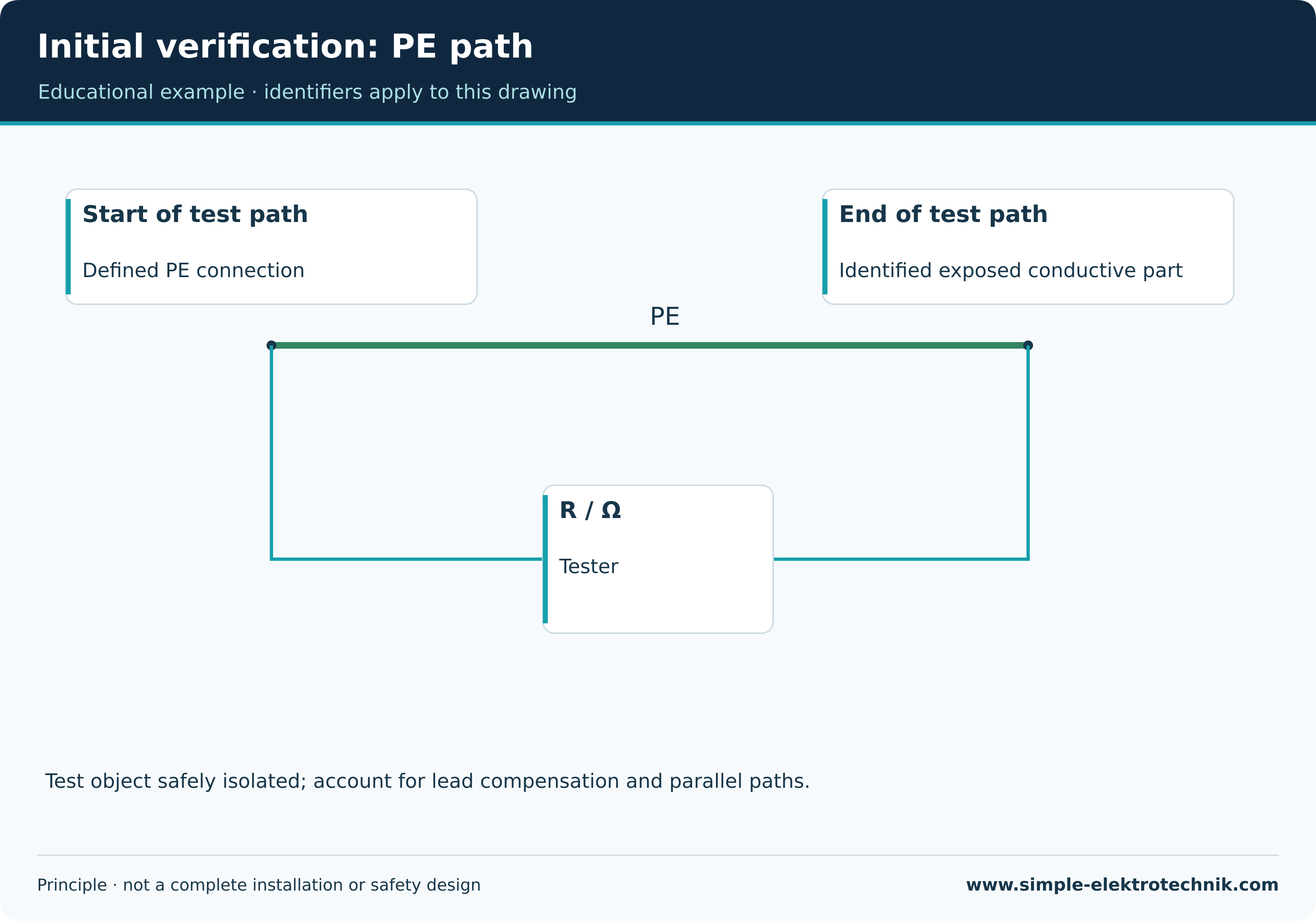
Protective conductor testing examines the intended conductive path. Length, cross-section, connections and parallel paths affect assessment. A buzzer is not a universal proof of suitably low resistance.
Measurement points must answer the intended question. Testing between two well-connected parts inside a board does not establish continuity at the far end of the new circuit. Inclusion of protective bonding depends on the scope and protective measure.
Insulation resistance
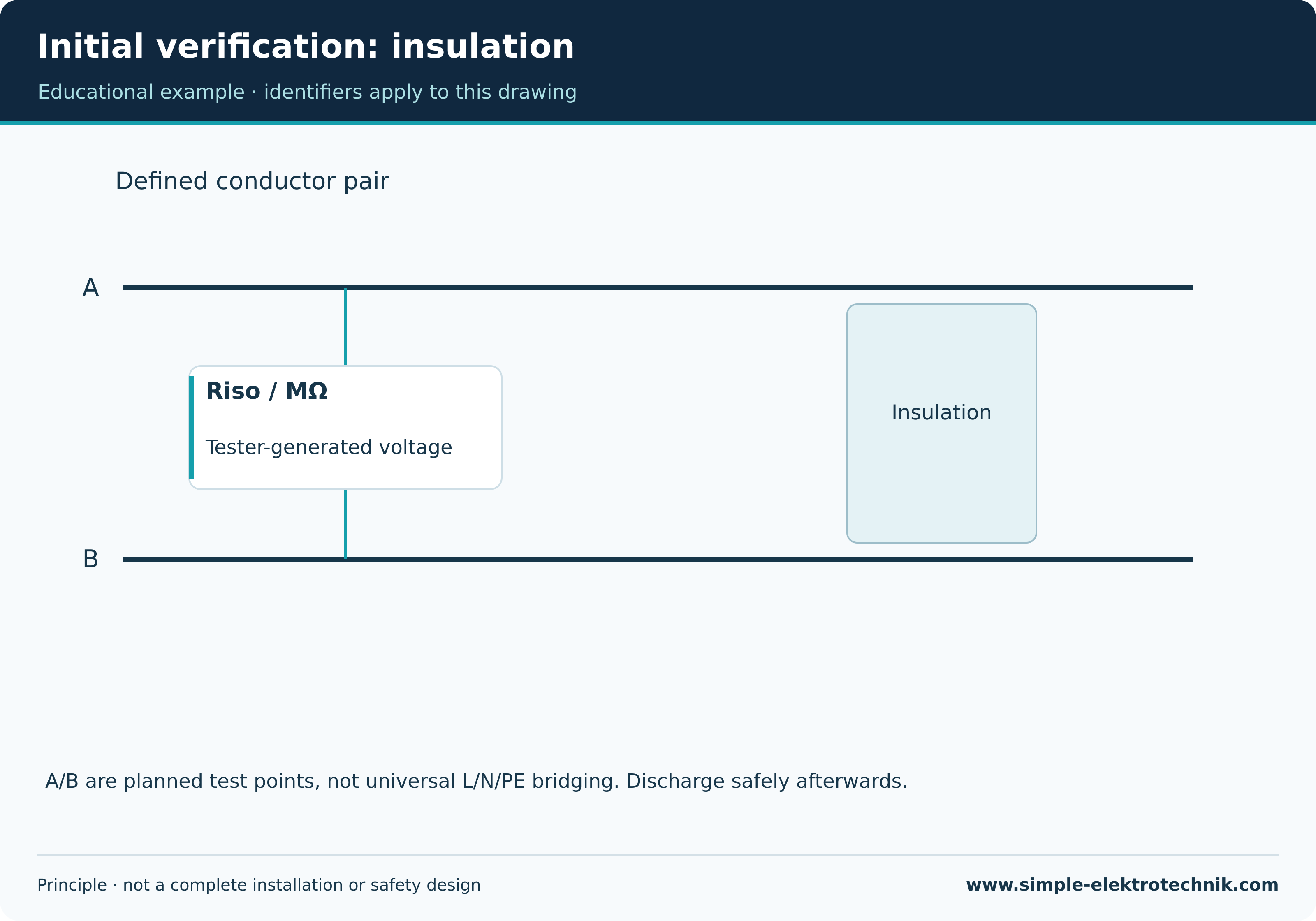
Insulation resistance testing examines separation between defined conductive parts. The tester itself generates a test voltage. Isolated from the normal supply therefore does not mean its test contacts are safe to touch during the test.
Electronic controls, surge protection, power supplies and connected loads are handled according to the method and manufacturer instructions. Selecting a lower voltage is not automatically an acceptable alternative. Grouping conductors is permitted only where appropriate to the defined method.
Capacitive parts may retain charge afterwards. Discharge and verification of a safe condition belong to the process. Temporarily disconnected conductors and equipment are restored systematically and included in the necessary completion checks.
Conductor identification and other protective arrangements
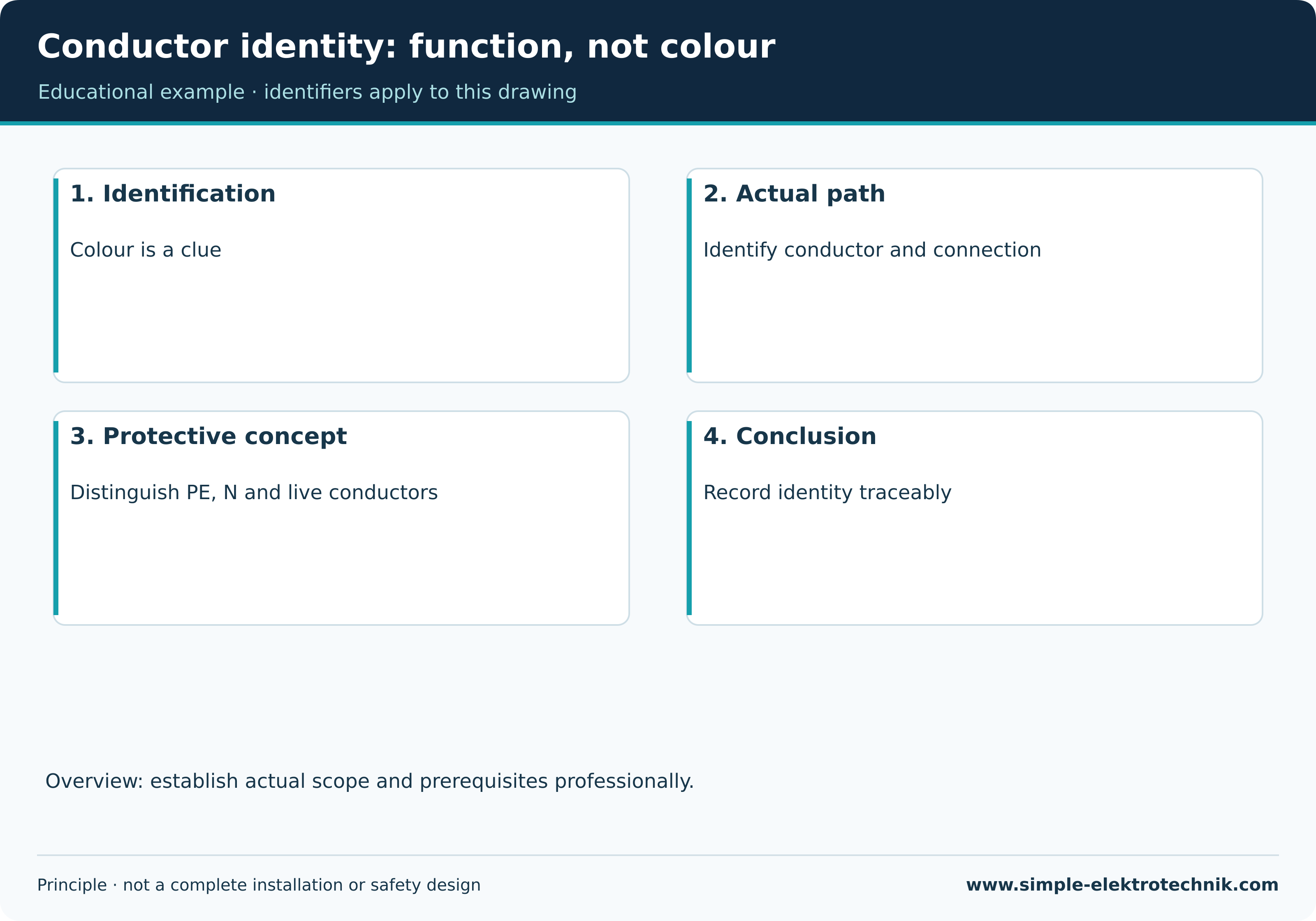
Conductor identification, polarity and other measures are verified as applicable. Actual conductor and equipment functions matter, not just insulation colours. A pure Schuko system, for example, does not guarantee a fixed L/N assignment at a connected appliance through plug orientation.
Electrical separation, SELV/PELV and special installation conditions may require further verification. Voltage drop may also need assessment. These items cannot be omitted simply because an automatic standard sequence does not prompt for them.
Initial verification: PE path
Initial verification: insulation
Conductor identity: function, not colour
Transition to tests requiring a supply
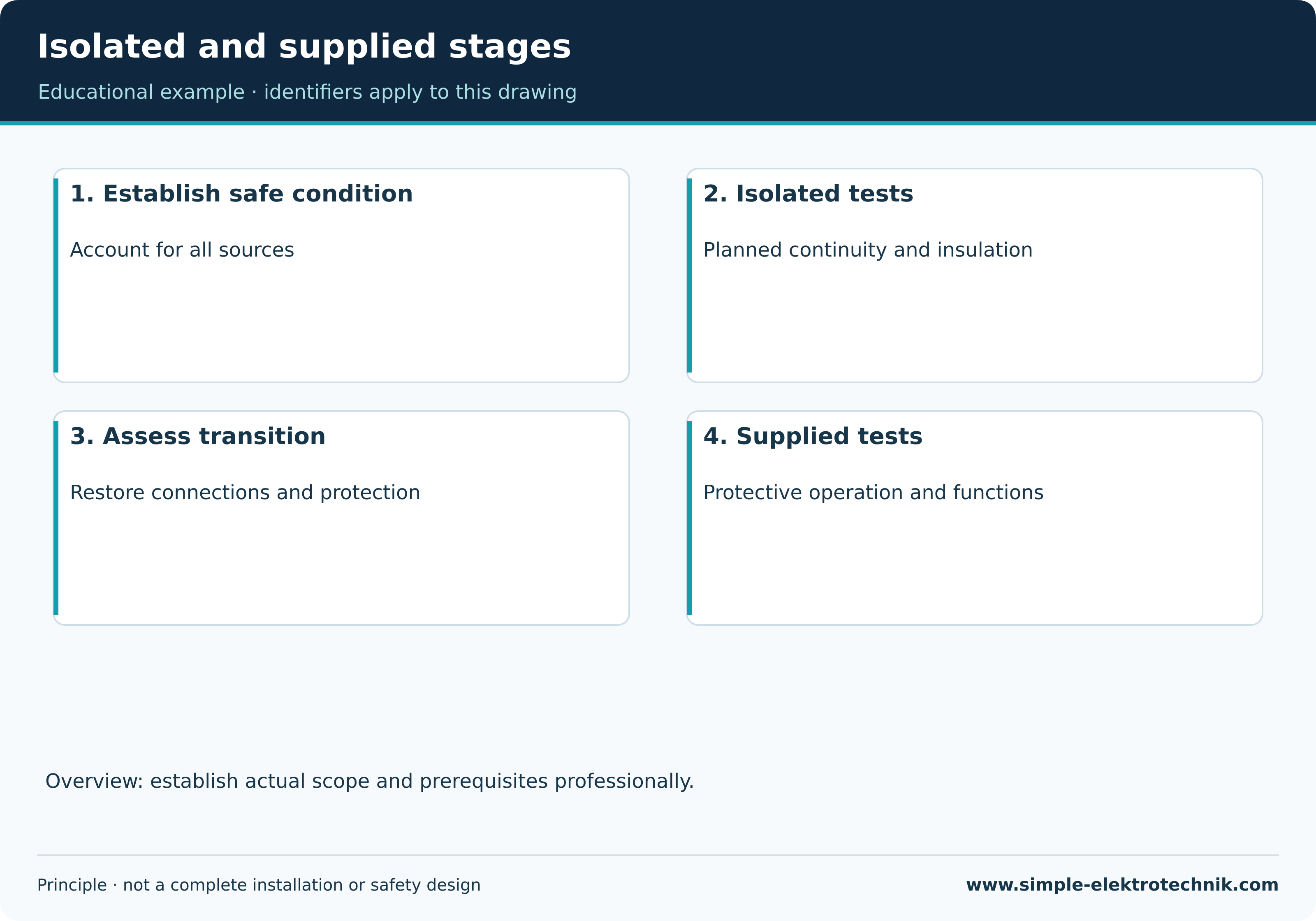
Some tests require the installation supply. Before that transition, the necessary preceding checks must have succeeded, temporary interventions must be resolved and people must be protected. The plan defines which parts may be supplied and which remain secured.
Permission to conduct a controlled test stage is not permission for normal use. Nor does a sequence illustration mean that one favourable reading authorises switching on. The necessary protections and operating conditions are installation-specific.
An automatic sequence can interrupt a supply or trip an RCD. Its effects on loads, data, controls and people must be considered beforehand. Restoration follows assessment of the resulting condition.
Isolated and supplied stages
Assess disconnection and additional protection
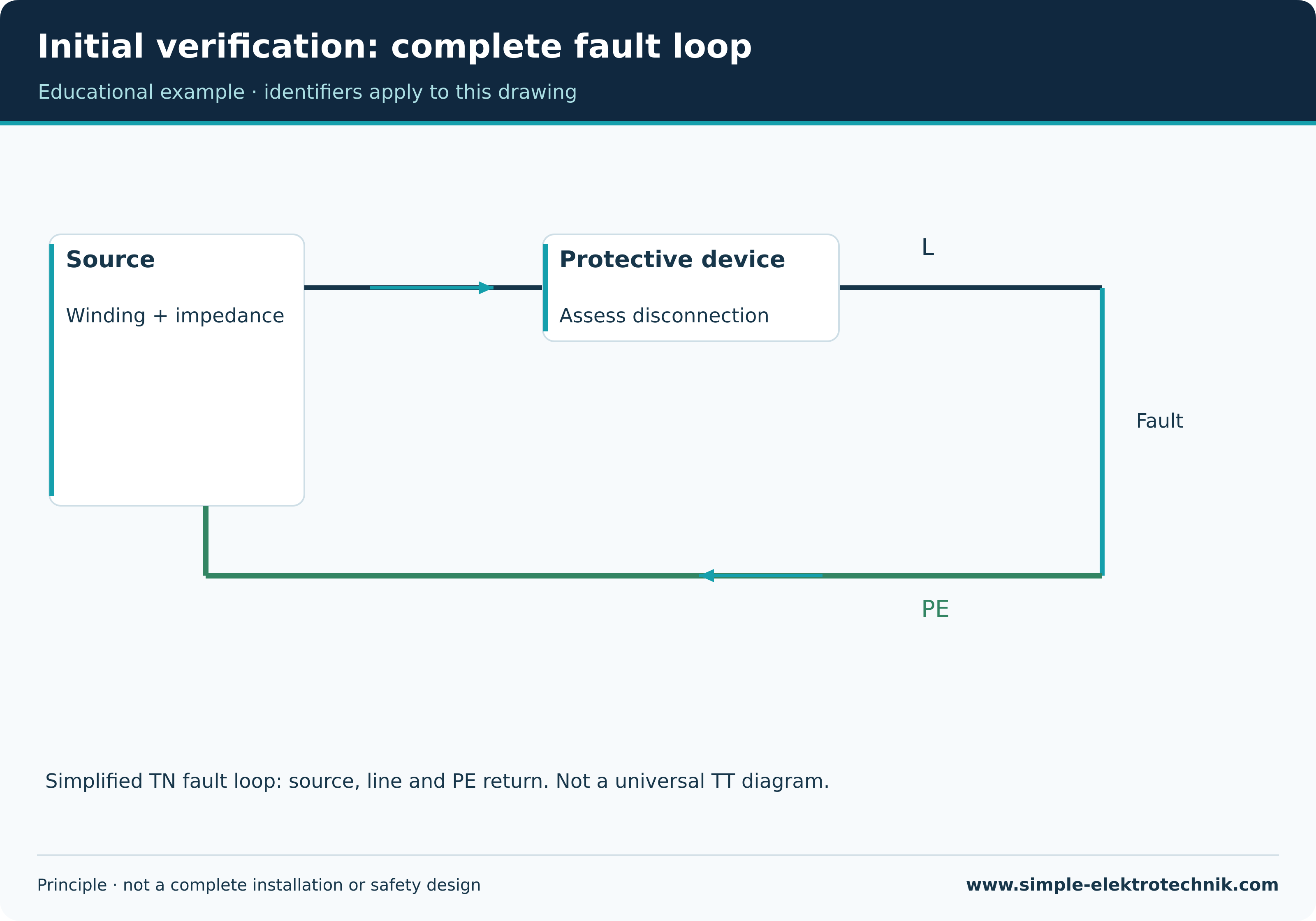
Loop impedance testing examines the complete relevant fault loop. Assessment depends on the earthing arrangement and the protective device relied upon. One universal ohmic limit for every socket would be misleading.
RCD testing uses a suitable programme. Device type, intentional delay where applicable, test waveform and conditions must match. The integral test button does not replace instrumented verification.
In a TT arrangement, the earth electrode can play a different role in the protective assessment from a TN example. The earth electrode testing guide explains methods and limitations. Neither a favourable electrode result nor an RCD that trips proves every protective measure is complete.
Initial verification: complete fault loop
Initial verification: RCD test principle
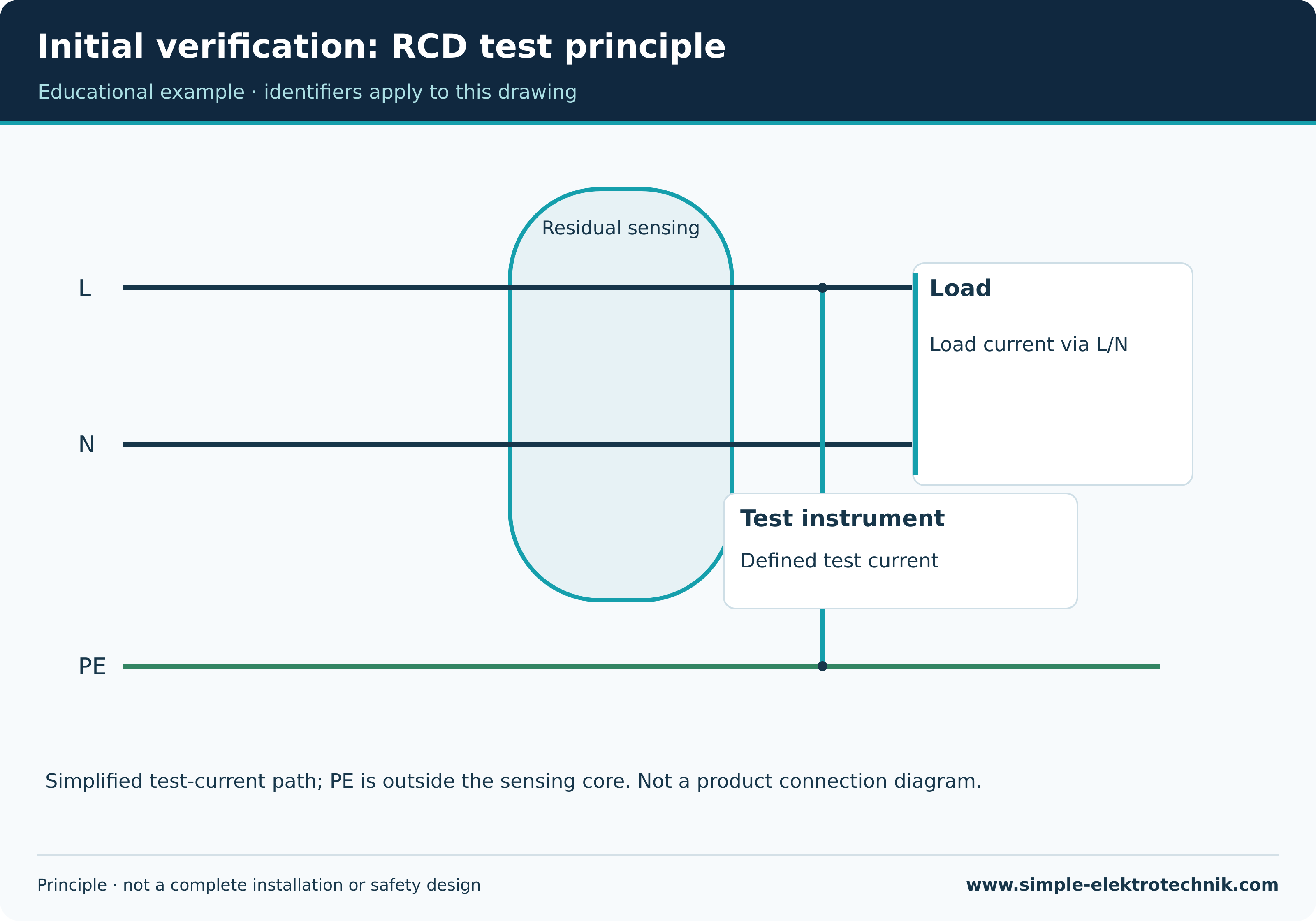
Voltage, phase sequence and functions
Voltage measurement helps assess the supply and reference points. Results need to identify the conductor pairs actually examined. One expected voltage does not exclude conductor errors or every defect in the protective system.
Where relevant, phase sequence is checked. A clockwise indication is not automatic proof of the required mechanical direction of an arbitrarily connected motor.
Functional testing examines intended operation. This can include control points, timing, stopping and interlocks. Safety-related machinery functions need their own applicable verification; an ordinary operational test does not replace it.
Which test answers which question?
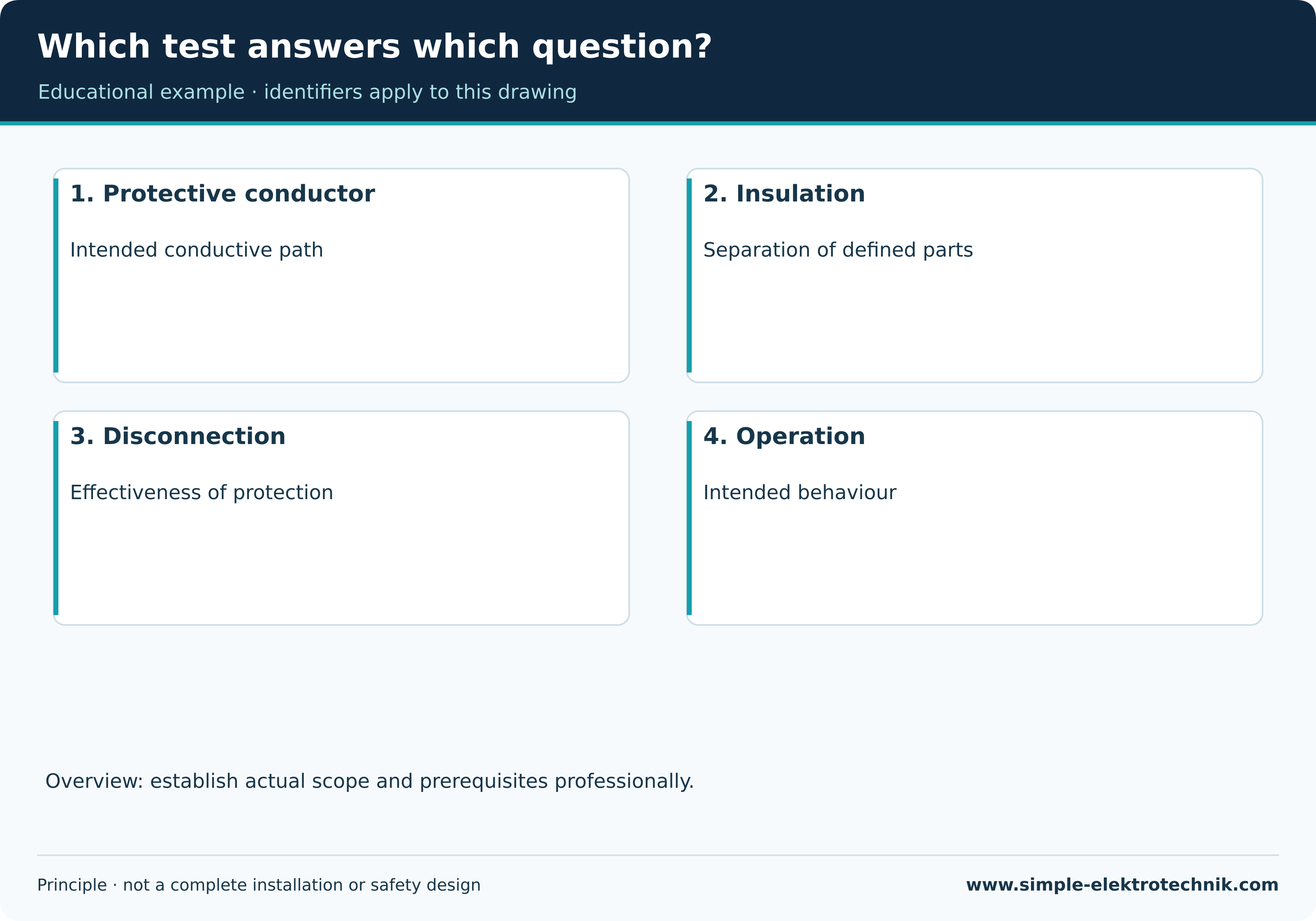
Worked example 1: a new socket circuit
Assume a new circuit supplies several sockets from an existing distribution board. The example intentionally gives no universal combination of protective rating, conductor size and acceptance limits. These belong to the actual design.
Start with the existing supply: are the earthing arrangement, protective conductor path, board condition, connection facilities and intended protective devices suitable for the extension? A spare module position cannot answer all of that.
During installation, inspect routes, terminals, conductor assignment, protective connections and entries. Identify the sockets with their circuit. Assess concealed parts before access is lost.
In the defined isolated condition, verify the necessary continuity, insulation and conductor assignment. Following successful preparation for supplied tests, complete the applicable protective and functional checks. Assign each location and result to the actual circuit and protective device.
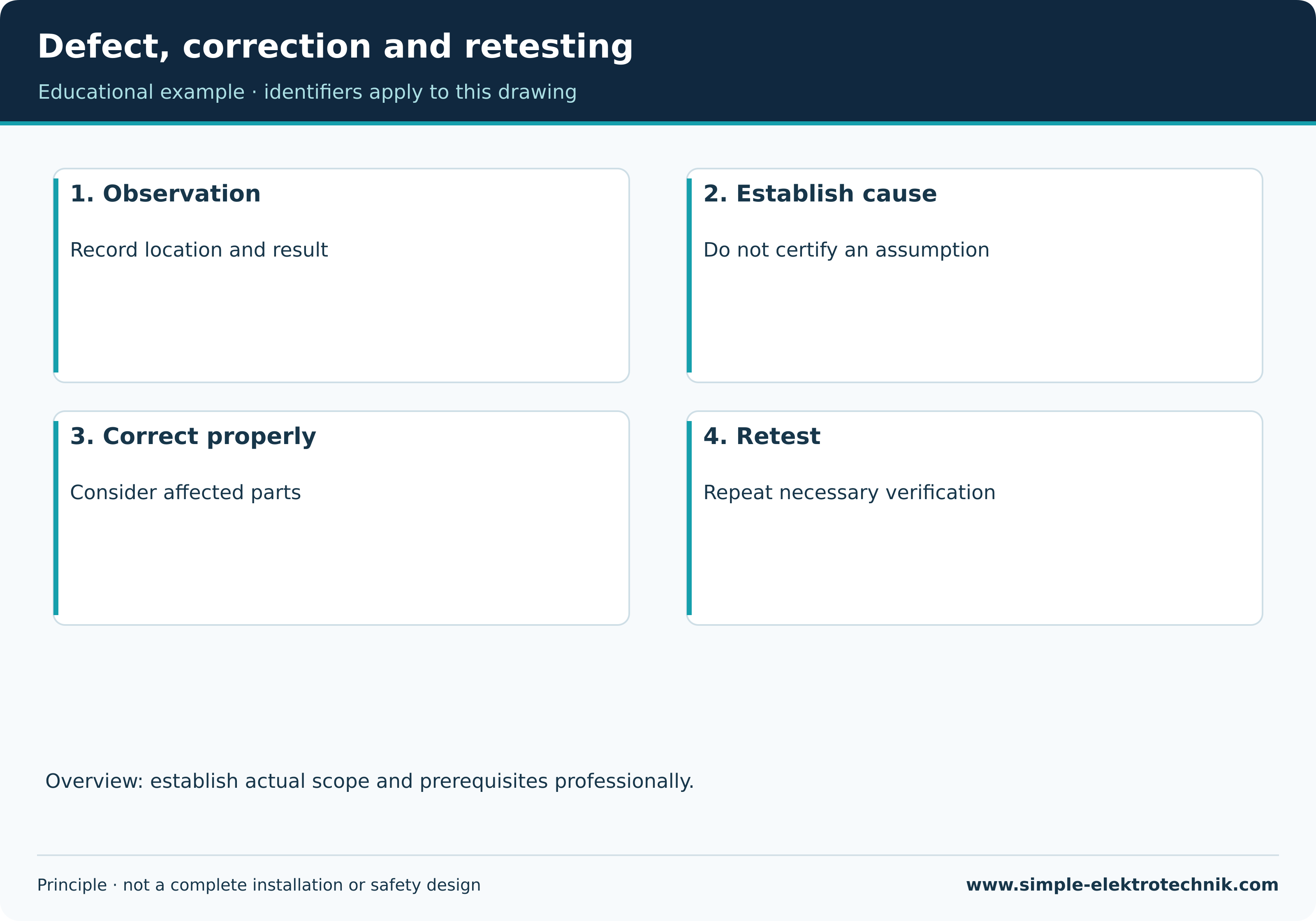
If one socket has no traceable protective conductor path, do not enter a favourable result from another socket. Investigate the cause, correct the defect and repeat the affected verification.
New circuit: consider the existing supply
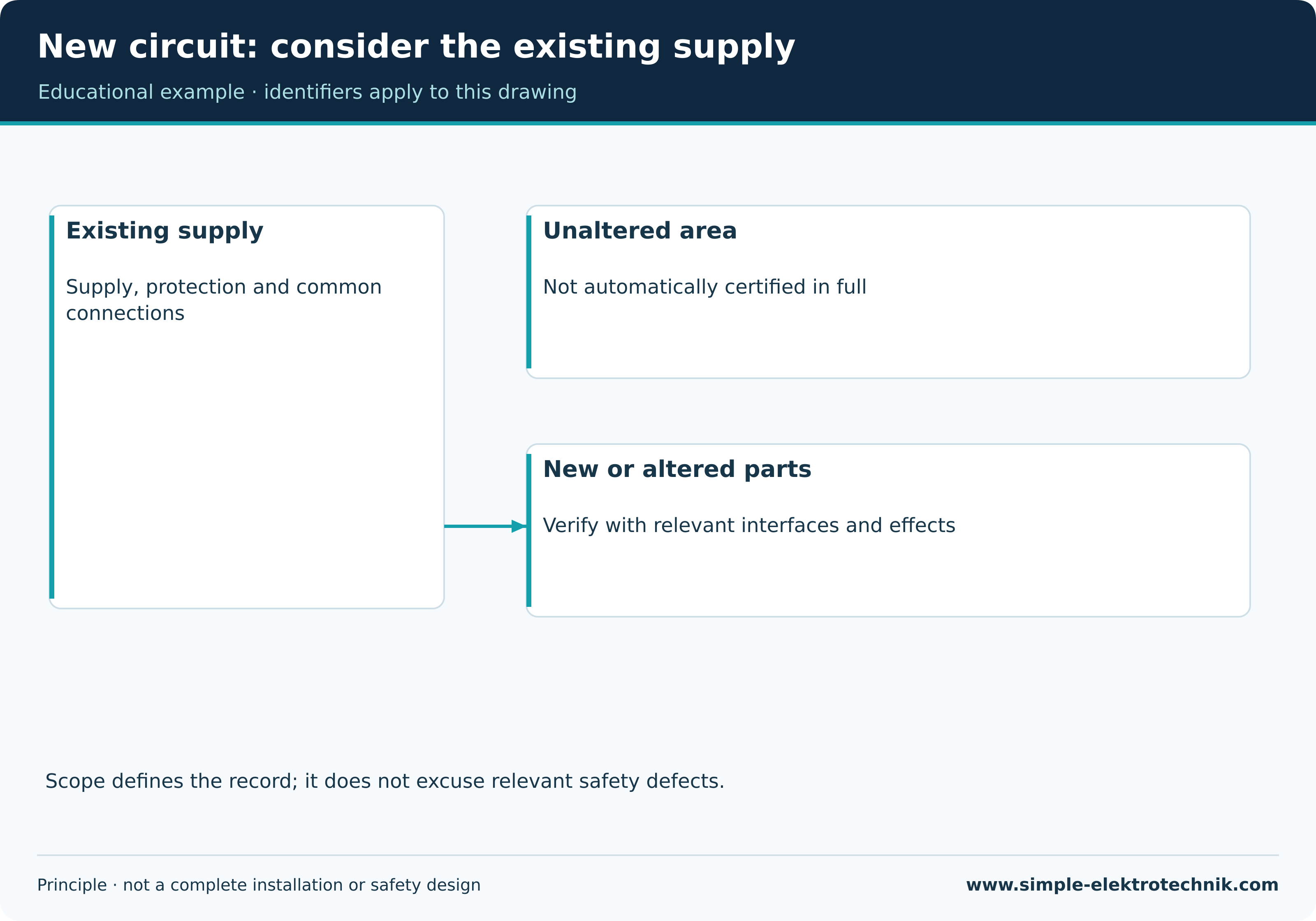
Worked example 2: extending an existing circuit
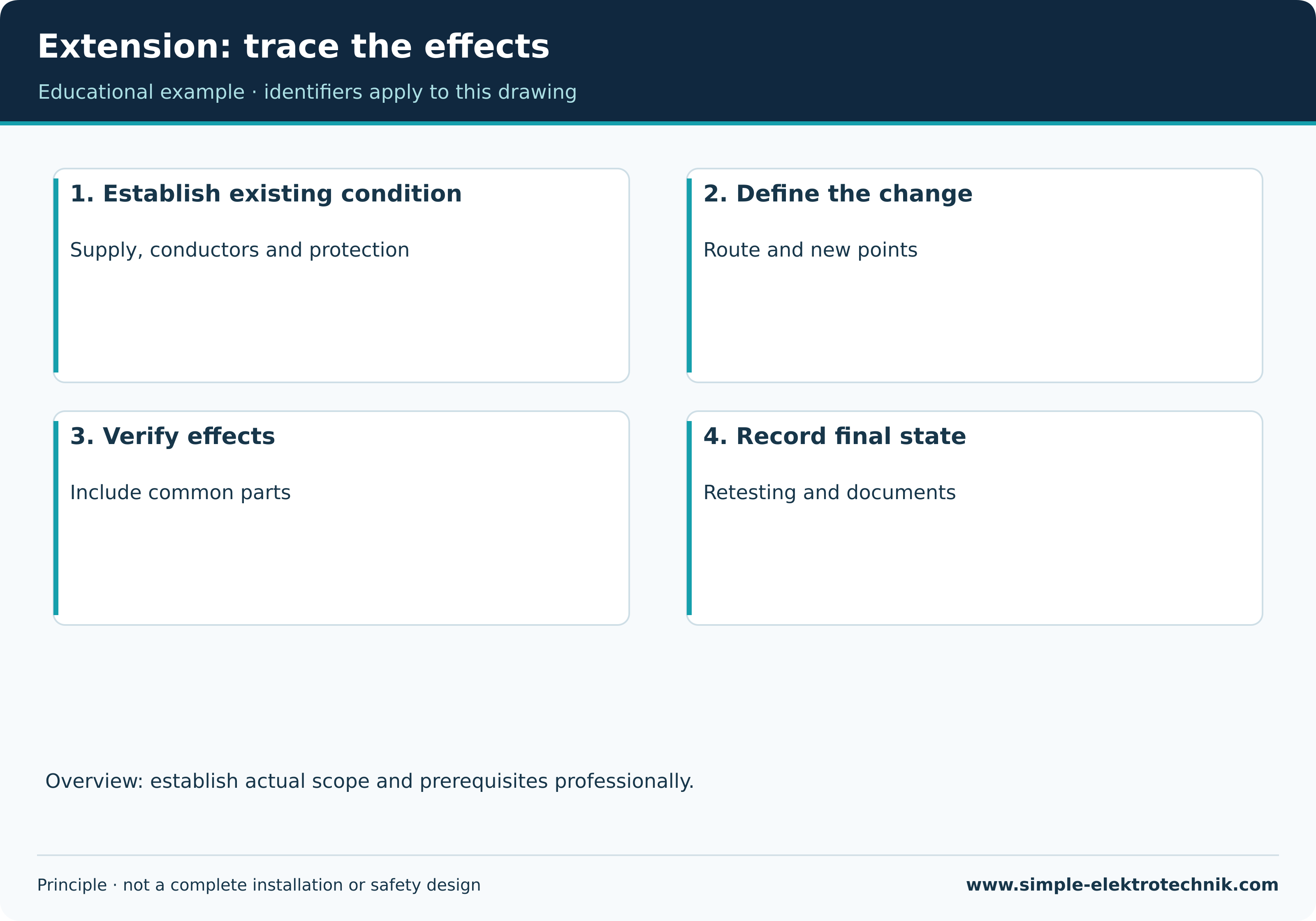
Now assume an existing circuit receives another junction and additional outlets. Establish the actual existing arrangement: conductor count, condition, protective measure, capacity and documentation. Old labels may be wrong or outdated.
The scope includes the alteration and relevant common parts. An extra section can affect the protective conductor path, fault loop and voltage drop. Intended loading also needs assessment.
An inaccessible unverified part is not silently marked as passed. Explain the limitation and its consequences. Where the necessary evidence for intended use is missing, an assumption cannot replace it.
After correction, decide which earlier results the intervention affects. Reopening a connection may require more than retesting the original suspect point. The final record describes what was actually verified and what remains outside its scope.
Extension: trace the effects
Evaluate results rather than copying numbers
Assessment needs the result, unit, method, conditions and applicable requirement. Circuit identity and its protective device matter as much as the displayed number. Earlier values help only when conditions are comparable.
| Observation | Appropriate line of investigation |
|---|---|
| Very low protective resistance despite suspected interruption | Establish the measurement path and possible parallel connections |
| Unexpectedly low insulation resistance | Investigate connected loads, electronics, moisture and scope |
| Loop result inconsistent with protection | Check method, location, protective concept and possible conductor defects |
| RCD trips during loop testing | Consider existing leakage, RCD characteristics and instrument method |
| Results disagree with labels | Verify circuit identity before further assessment |
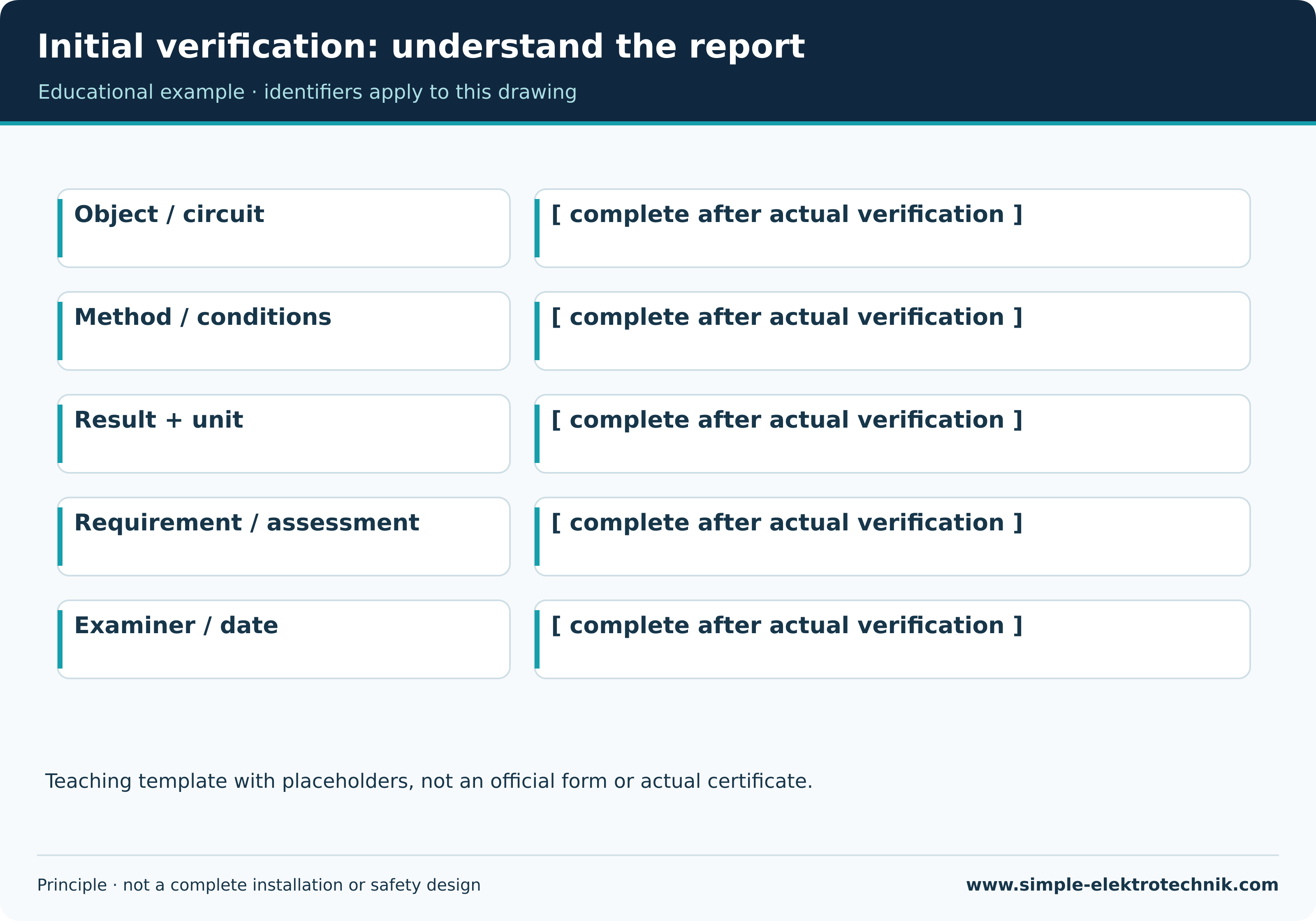
No real measurements are invented here. Report illustrations are labelled teaching templates with placeholders. Any numerical calculation is explicitly an educational example, not an installation approval.
Defect, correction and retesting
Records, defects and handover
A report records the reason, installation, scope, applied requirements, methods, results and assessment. Required details of the examiner, date, instruments, protective measures and documents are included. Mandatory particulars depend on jurisdiction and application.
Defects are described unambiguously and assigned to the affected parts. Retesting records the correction and necessary repeated verification. A failed result does not become a valid pass just by changing an instrument setting.
At handover, records must represent the final installation. These may include schedules, drawings, operating information and the report. A sticker or a tester screenshot is not a substitute for complete, traceable records.
Initial verification: understand the report
Common questions
Does every alteration require testing the entire house?
There is no universal answer. The alteration, its effects and relevant existing parts determine the necessary scope. The report must not present an unverified complete installation as fully verified.
Is a simple socket tester sufficient?
It may provide particular indications. It cannot replace the required combination of inspection, suitable tests and assessment. Detectable faults depend on its actual functions.
Can an automatic sequence decide everything?
No. A tester does not automatically know the complete arrangement, every manufacturer requirement or the correct scope. Programme selection, safe execution and assessment remain professional tasks.
Who may test and sign?
Country, activity, competence and any required authorisation determine this. Owning an installation tester is not enough. Austrian and Swiss legal and organisational provisions must not be merged.
Does passing mean a fault can never occur?
No. The evidence relates to the verified scope and condition. Appropriate operation, maintenance and subsequent required inspections remain necessary.
Related guides
Sources and technical context
- Fluke 1672/1673 FC/1674 FC – Users Manual, Rev.4,06/2026
- Arbeitsinspektion: kommentierte ESV 2012
- OVE: neue Ausgabe OVE E 8101:2025
- DKE: DIN VDE 0100-600 Kurzdarstellung
- ESTI: Erstprüfung, Schlusskontrolle und Sicherheitsnachweis
Sources support this explanation. Public standard summaries do not replace the complete standard. Retain national context and equipment conditions.