

Inspection and testing

A reading becomes meaningful together with its method, test object and conditions. Here we explain quantities and terminology found in instruments, verification records and the associated guides.
Continuity, insulation resistance and loop impedance answer different questions. One favourable result replaces neither the other required tests nor a clear assessment. The full testing guides explain each method in context.

How these terms connect
Measured quantities, test methods and the limits of an individual reading. The short definition supports quick lookup. Open an entry for its example, important distinctions and useful references. Related terms link to further entries in the glossary.
The linked guides explain applications in greater detail. This glossary explains terminology and replaces neither product documentation nor assessment of an actual installation.
Look up a term
14 terms found
C
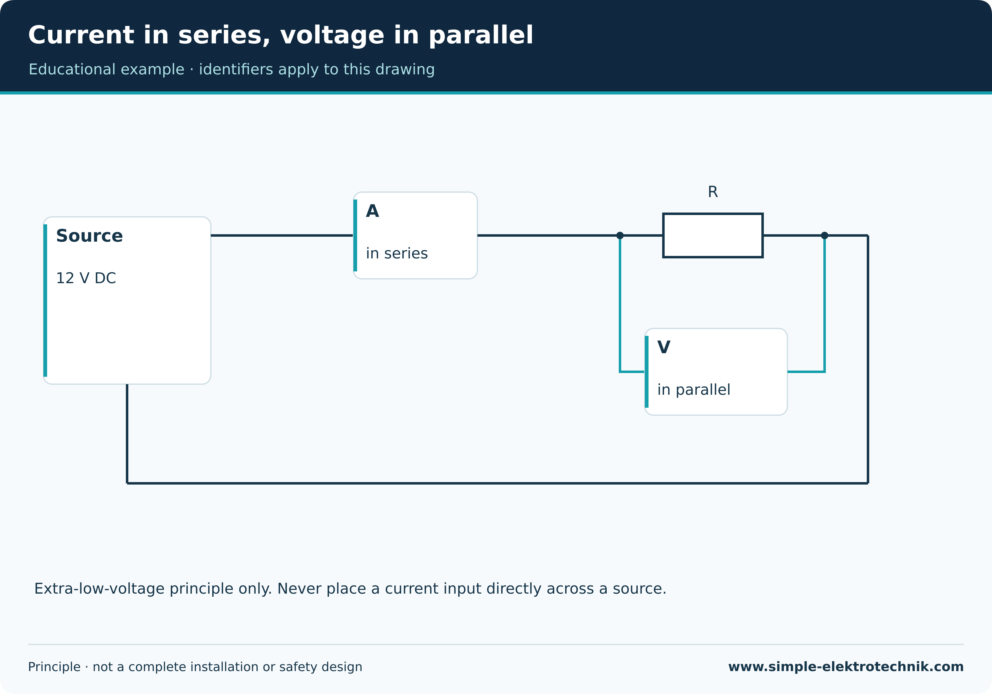
Current measurementCurrent measurement determines current in a defined conductor or group using a suitable method.
An instrument inserted into a circuit and a current clamp have different conditions. With a clamp, the conductors enclosed together are decisive.
Example
When a suitable clamp encloses outgoing and returning conductors together, their load-current effects may cancel in the sensing principle.
Important distinction
A current input must not be placed across a source like a voltmeter. Clamp type, conductor group and desired quantity must be clear.
E
Electrical continuityElectrical continuity describes an existing electrical connection along a defined test path.
The suitable test method and assessment depend on the task. Test leads, contact points and parallel conducting paths may affect the result.
Example
A protective-conductor test examines the intended protective path between defined points.
Important distinction
A continuity beep from an arbitrary multimeter does not automatically prove required protective-conductor quality. A parallel path can conceal a break.
F
Fault-loop impedanceFault-loop impedance describes the impedance of a considered closed fault path, including the relevant supply and return paths.
Its result depends on earthing arrangement, method and protective concept. Under suitable assumptions, prospective fault current can be derived.
Example
A simplified TN fault loop includes source, line conductor and intended metallic protective return.
Important distinction
A loop measurement is not an isolated earth-electrode test. A TN example cannot simply be transferred to TT or IT.
I
Initial verificationInitial verification examines a new or appropriately altered electrical installation before its intended commissioning under applicable requirements.
Inspection, functional testing, measurement, assessment and recording belong together. The scope and interfaces of an alteration need clear definition.
Example
A new circuit is considered together with its required connections and effects on the existing supply.
Important distinction
A successful functional check or one reading does not replace required complete initial verification. Country and test object must not change unnoticed.
Insulation resistanceInsulation resistance describes the electrical resistance across a considered insulation path between defined points.
Measurement uses a suitable test procedure under specified conditions. Connected electronics, surge protection and other components may require special preparation.
Example
A result is recorded with the test object, measurement points, test voltage and assessment.
Important distinction
A favourable value for one conductor pair does not prove every other insulation path. An RCD test button is not an insulation measurement.
M
Measurement categoryMeasurement category identifies instrument suitability for specified stresses within an electrical supply environment.
Category and associated voltage rating must be considered together. Leads, accessories and actual conditions also form part of selection.
Example
An instrument used in distribution needs the appropriate combination of category and voltage rating.
Important distinction
The highest marked voltage alone does not establish a suitable location of use. A CAT marking also does not prove every required measurement function.
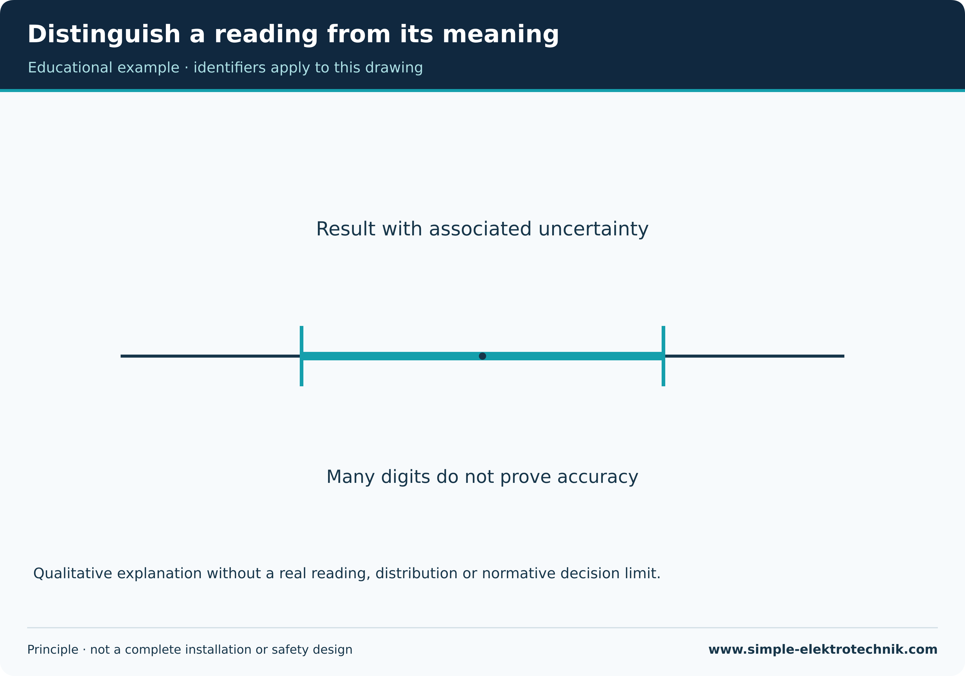
Measurement uncertaintyMeasurement uncertainty describes uncertainty associated with a measurement result on the available information.
Instrument, method, contacts, environment and other influences may contribute. Calibration determines relationships to references; it does not automatically mean adjustment.
Example
A result near a decision limit needs assessment using the intended decision process and its uncertainties.
Important distinction
Many decimal places do not prove equivalent accuracy. A calibration certificate does not replace pre-use function and condition checks.
O
Operating timeOperating time describes the interval between a specified triggering event and the device’s intended response.
The start and end points depend on the test procedure. Device operating time and the complete required disconnection time of a protective concept need careful association.
Example
In RCD testing, current waveform, operating conditions and the corresponding time result are assessed together.
Important distinction
A single millisecond value without device type and test conditions cannot support a reliable pass/fail judgement. Do not assume a universal time limit.
P
Phase-sequence testA phase-sequence test examines the phase order at a defined point in a suitable multiphase system.
Connection, suitability and interpretation follow the instrument instructions. The indication describes the electrical order, not directly every mechanical machine motion.
Example
A motor may need a separate rotation check despite the expected phase sequence because of its actual connection.
Important distinction
A clockwise phase sequence is not complete installation verification. Conductors must not be swapped experimentally without a safe professional procedure.
Protective conductor verificationProtective conductor verification examines the intended protective connection and its required properties using a suitable method.
Test points and intended path must be clear. Parallel paths can produce a favourable result even when the intended connection is broken.
Example
A visible enclosure screw is not assumed to be a suitable test point without establishing its actual electrical function.
Important distinction
This is different from earth-electrode or insulation testing. One favourable result does not automatically certify the whole installation.
R
Rated residual operating currentRated residual operating current is a specified RCD characteristic, commonly denoted IΔn.
It differs from rated load current, actual leakage current and the operating current found by a test. Associated conditions are specified by the device and procedure.
Example
An RCD has separate markings for its load-current rating and residual-current protective characteristic.
Important distinction
The marking is not a measured installation value. A suitable rating also does not replace verification of the complete protective measure.
Resistance measurementResistance measurement determines resistance between defined points under the measurement method’s conditions.
Test current, contacts and possible parallel paths influence the value. An ordinary ohmmeter is not intended for arbitrary connection to a supplied circuit.
Example
A defined resistor may be measured across its terminals in a suitable safely isolated teaching setup.
Important distinction
Resistance, insulation and loop-impedance measurements are different methods. One range does not automatically perform the other verification tasks.
T
Test currentTest current is a current generated or used by an intended test method to examine a particular property.
Its type, magnitude, waveform and duration form part of the method. A continuity-test current serves a different purpose from an RCD test current.
Example
A suitable instrument can generate a defined residual current to test an RCD.
Important distinction
Test current is not automatically load current or rated current. Values from different procedures cannot be compared without context.
V
Voltage measurementVoltage measurement determines the electrical potential difference between defined points.
Mode, range, input properties and safe instrument selection must suit the task. A reading always relates to the actual measurement points.
Example
In a simple extra-low-voltage teaching diagram, voltage is measured across the considered resistor.
Important distinction
An arbitrary measurement is not complete verification of absence of voltage. A wrongly selected current input connected across a source can create a dangerous fault.
No matching term. Try another spelling or select all topics.