
Switching, control and circuit diagrams

Diagrams often show contacts, coils and control paths in positions different from their physical locations. The right terminology helps explain the function and the state being depicted.
Normal state and actuation are particularly important: an NC contact is closed in its specified normal state. The German term Serienschalter does not mean its lamps are in series. Examples and function drawings explain these distinctions.

How these terms connect
Contacts, controls and the language of circuit diagrams. The short definition supports quick lookup. Open an entry for its example, important distinctions and useful references. Related terms link to further entries in the glossary.
The linked guides explain applications in greater detail. This glossary explains terminology and replaces neither product documentation nor assessment of an actual installation.
Look up a term
17 terms found
C
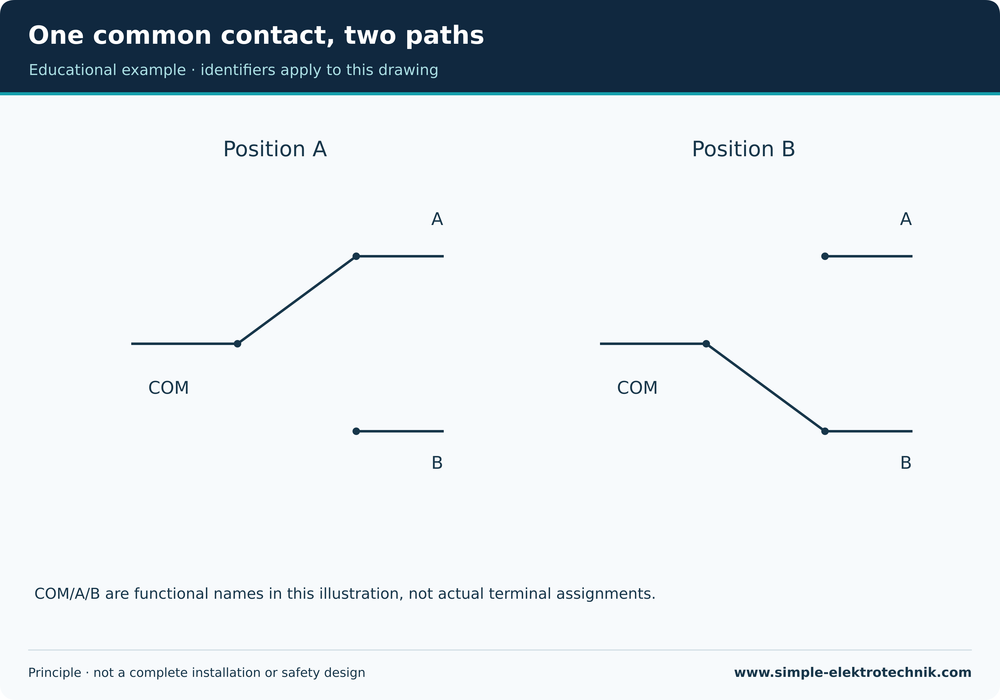
Changeover contactA changeover contact connects a common contact to one of two other contacts depending on its position.
Actual terminal markings and transfer behaviour depend on the device. The common contact cannot be inferred solely from its physical position.
Example
Two suitable changeover switches can form part of a lighting circuit operated from two locations.
Important distinction
A changeover is not the same as two independently operated NO contacts. An arbitrary terminal must not be assumed to be neutral.
Circuit diagramA circuit diagram represents components and their electrical relationships using symbols and connecting lines.
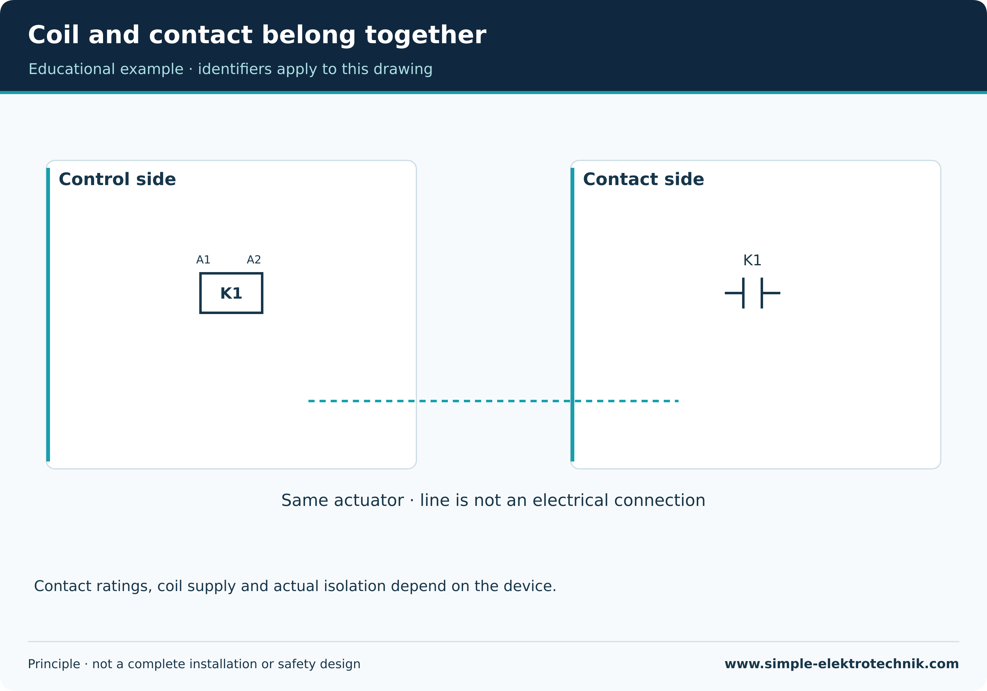
A schematic explains different relationships from a scaled assembly drawing. The representation, device identification and depicted state must be understood.
Example
A control drawing may show a coil and its associated contacts in different positions even though they belong to one device.
Important distinction
A symbol’s position does not establish a universal physical terminal position. A principle illustration does not replace actual device documentation.
Circuit symbolA circuit symbol is an agreed graphical representation of an electrical component or function.
Its meaning follows from the drawing convention and context. Additional markings can identify the device, function and terminal relationship.
Example
NC and NO symbols distinguish the specified normal states of contacts.
Important distinction
An invented protection-class symbol can mislead. Established markings must not be replaced with decorative variants having a different meaning.
ContactorA contactor is a suitably rated remotely operated switching device, commonly used for electrical loads.
Main contacts switch the intended load; auxiliary contacts may perform control functions. Coil rating, utilisation category and load type need suitable selection.
Example
A motor contactor can be controlled through start and stop buttons in a suitable control circuit.
Important distinction
A contactor does not automatically replace overload or short-circuit protection. Its off state is not a general proof of safe isolation either.
Control circuitA control circuit handles the intended commands, permissives and feedback of a circuit.
It may contain pushbuttons, contacts, coils and electronic controllers. Supply voltage and protection must match the actual construction.
Example
Start and stop pushbuttons and a holding contact may together form the intended contactor-coil path.
Important distinction
Control circuit does not automatically mean extra-low voltage or safe touch conditions. Its supply must be expressly considered during safe working.
E
Emergency stopEmergency stop is an intended emergency function for stopping hazardous motion or processes within the machine concept.
Actuation, evaluation and stopping need suitability for the actual risk assessment. Resetting must not cause an unintended restart.
Example
A conspicuous actuator may form part of the function but is not itself a complete safety concept.
Important distinction
Emergency stop and emergency switching off are different tasks. An ordinary stop button or red actuator is not a general proof of function.
H
HysteresisHysteresis means a system’s state depends on the preceding history of its input.
In a switching device, this may produce different on and off thresholds. It can avoid repeated switching from small fluctuations around one threshold.
Example
A temperature controller may switch on below a lower threshold and off above a higher one.
Important distinction
Hysteresis is not simply a time delay. A device may have both properties separately.
I
InterlockingInterlocking prevents specified impermissible combinations of circuit or machine states.
It can be electrical, mechanical or implemented by a suitable control concept. Its function also needs assessment under the considered fault conditions.
Example
In reversing contactor control, the impermissible simultaneous energisation of both direction paths must be prevented.
Important distinction
A software condition alone is not a general safety demonstration. Required interlocking methods and stopping conditions depend on the actual application.
N
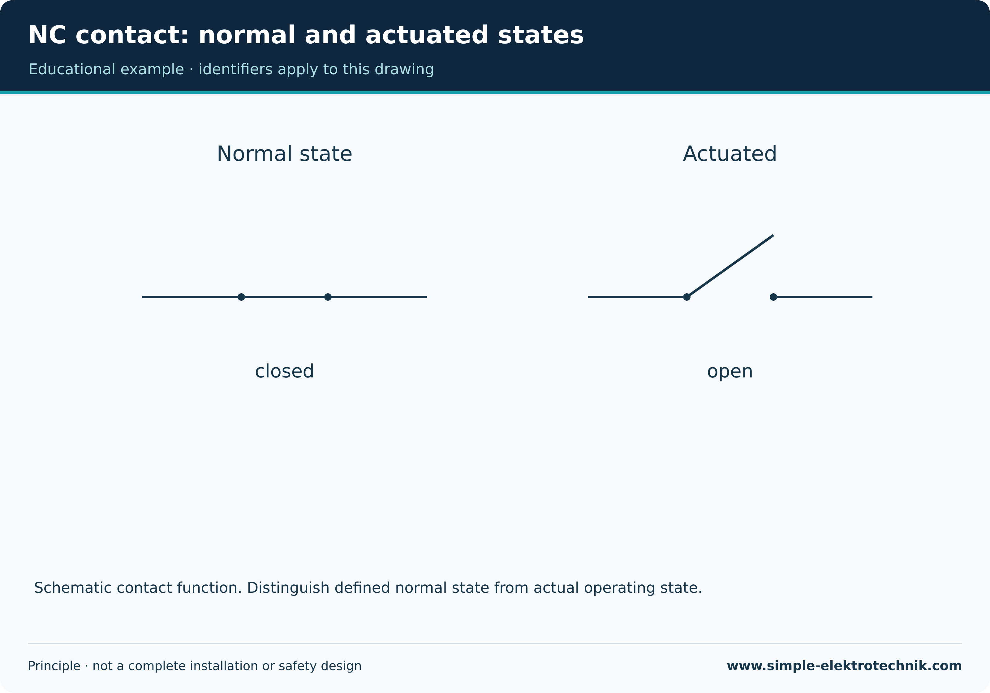
Normally closed contactA normally closed contact is closed in the specified unactuated normal state and opens when actuated.
Determine contact function from its symbol and device documentation. Terminal numbers can help but do not replace identification of the actual device.
Example
An ordinary stop pushbutton may use an intended NC contact to interrupt the control-current path.
Important distinction
An NC contact in a stop path does not alone provide a validated emergency stop. Safety functions require a complete suitable concept.
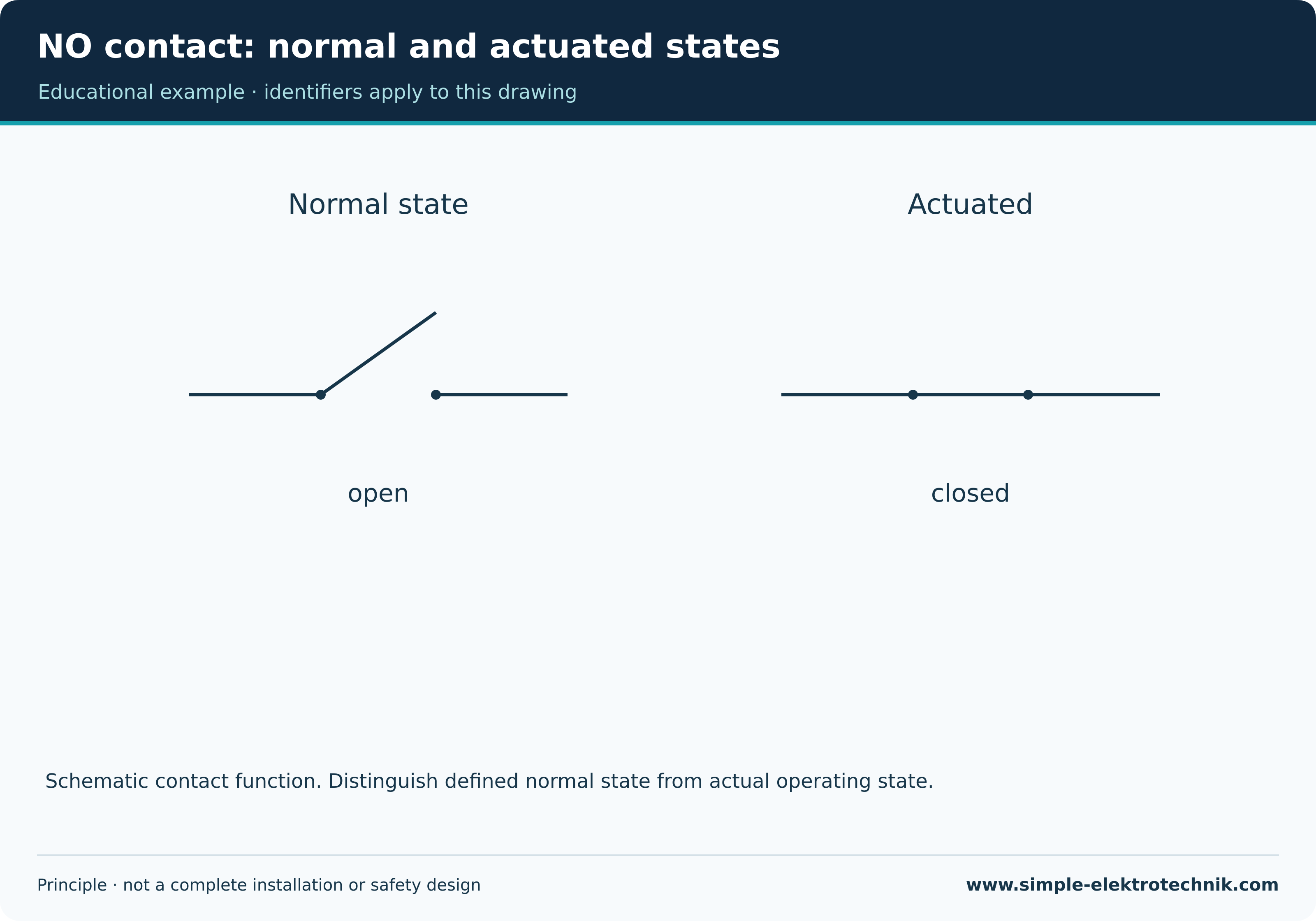
Normally open contactA normally open contact is open in the specified unactuated normal state and closes when actuated.
The symbol refers to that defined state. For relays and contactors, association with the actuator matters; switch drawing conventions also need consideration.
Example
A start pushbutton with an NO contact can close a control-current path when pressed.
Important distinction
NO does not describe an arbitrary present operating state. Distinguish the circuit’s normal-state convention from the actual device state.
P
Power circuitThe power circuit carries the electrical energy intended for the load within a switching arrangement.
Conductors, main contacts and protective devices are selected for actual requirements. The control may have separate ratings and supplies.
Example
In a motor starter, the load supply passes through the intended main contacts to the motor.
Important distinction
An off control circuit does not prove a dead power circuit. Conversely, separately supplied control sections may remain live.
PushbuttonA pushbutton generally operates a contact while actuated and returns to its normal state afterwards.
Its normal state may provide an NC, NO or other intended contact function. What the connected control does with the impulse is a separate matter.
Example
A short impulse can toggle an impulse relay while the pushbutton itself returns.
Important distinction
Pushbutton does not imply capacitive touch sensing. Mechanical buttons and electronic touch surfaces should be distinguished.
R
RelayA relay switches a circuit in response to a control signal. Electromechanical relays use an actuator and contacts; other designs operate electronically.
Control and load sides have their own ratings. Whether isolation exists, and of what kind, must follow from actual construction and documentation.
Example
A suitable relay can use a control signal to switch a load with different ratings.
Important distinction
A relay is not automatically a power contactor or safety relay. Solid-state relays may also involve off-state leakage and heat losses.
S
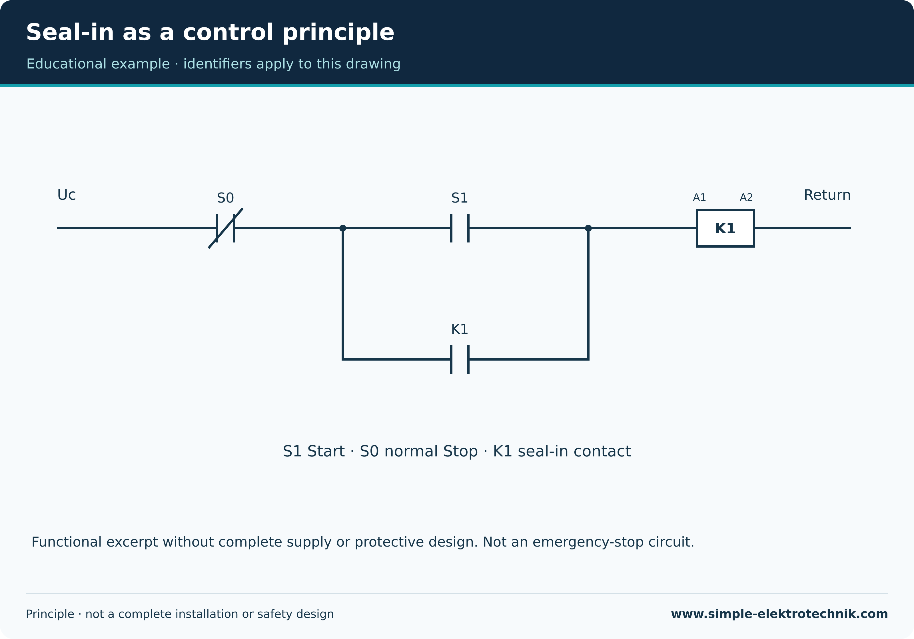
Seal-in circuitA seal-in circuit maintains an intended control state after a start impulse ends, while required conditions remain present.
In classic contactor control, an auxiliary NO contact can bypass the start contact. The stop path and intended protective conditions must still be able to release the circuit.
Example
After Start is released, K1 remains energised if its holding contact and other conditions maintain the coil-current path.
Important distinction
Seal-in is not an uninterruptible power supply. Behaviour after supply loss and restoration depends on the complete control concept.
Strapping wires in two-way switchingStrapping wires connect the relevant changeover contacts of a two-way lighting circuit. With intermediate switching, they also pass through suitable intermediate switches.
Their association follows from the diagram, device markings and actual routing. A simple two-location circuit has two such interconnecting paths.
Example
Switch positions determine whether the selected path to the lamp is complete.
Important distinction
These wires are not inductively coupled transformer windings. Translating the German term as coupled conductors is misleading here.
SwitchA switch makes, breaks or transfers an electrical connection.
Construction and actuation determine available contacts and whether their state is retained. Switching capacity and suitable load type inform selection.
Example
A maintained light switch retains its position after release.
Important distinction
An ordinary switch is not automatically a suitable isolating device. Its visible position also does not prove a dead work area.
T
Two-gang one-way switchA German Serienschalter has two independently operated switching functions for intended circuits or load branches.
The actual internal connection and terminal arrangement follow from the device. Two rockers can for example control two lighting groups separately.
Example
A luminaire with two separately supplied groups may be controlled according to its appropriate circuit.
Important distinction
This device name does not establish a series connection of lamps. A literal English translation as series switch is often misleading.
No matching term. Try another spelling or select all topics.